Microcontroller system and method for safety-critical motor vehicle systems and the use thereof
A technology of micro-controllers and motor vehicles, applied in response to error safety measures, instruments, generation of response errors, etc., can solve the problems of great cost pressure on all components, and achieve the goal of reducing manufacturing costs, reducing quantities, and reducing R&D costs Effect
- Summary
- Abstract
- Description
- Claims
- Application Information
AI Technical Summary
Problems solved by technology
Method used
Image

Examples
Embodiment Construction
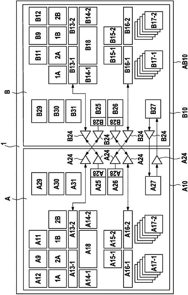
[0028] exist figure 1 In the description of the examples and embodiments only those components important for the understanding of the invention are discussed.
[0029] figure 1 An embodiment of a microcontroller system according to the invention is shown, which is implemented as a combination of a multi-core (multi-core) and multi-chip system on a single chip or silicon substrate. The microcontroller system here comprises subsystem A and subsystem B, which can each be implemented as a single-core or multi-core system and—except for coupling based on a common silicon substrate—physically separated and have a separate voltage source A11 , B11 and system clock supply means A12, B12. In order to improve functional safety, the two subsystems A and B implement, for example, a two-channel safety architecture with redundant cores 1A, 2A and 1B, 2B and memory buses A13-1, A13-2, B13-1, B13-2 , RAM memories A14-1, A14-2, B14-1, B14-2 and comparison units A15-1, A15-2, B15-1, B15-2. ...
PUM
 Abstract
Description
Claims
Application Information