
Auxiliary leveling device for pressing of rivets

A leveling device and rivet technology, which is applied in printed circuit manufacturing, printed circuit, multi-layer circuit manufacturing, etc., can solve problems such as poor quality, rivet cracking, uneven rivets, economic losses, etc., and achieve high flatness and uniformity High performance, precise pressing position, and space-saving effects

Inactive Publication Date: 2017-06-06
HUIZHOU ZHONGJING ELECTRONICS TECH CO LTD
View PDF10 Cites 2 Cited by
  • Summary
  • Abstract
  • Description
  • Claims
  • Application Information

AI Technical Summary

Problems solved by technology

[0002] After the PCB multi-layer board is nailed by the rivet machine, there may be problems such as uneven rivet opening or the selection of rivets that are too long to be higher than the board surface, which will easily cause poor quality problems such as copper wrinkles near the pressed rivet position; however, press The traditional method of knocking flat with an iron hammer is prone to knocking into the unit, scratching the browning layer or copper shavings falling into the unit and causing a short circuit
Existing rivet machines generally use simple punches for punching, which do not have guidance for the rivet blooming, and cannot control the uniformity and smoothness of the rivet blooming, and different circuit boards require different rivet positions, often requiring Several or even dozens of riveting machines are used for riveting, which greatly increases the cost. In addition, the riveting machines are likely to cause scratches on the surface of circuit boards or even scrap them, resulting in economic losses.

Method used


Image

  • Auxiliary leveling device for pressing of rivets
  • Auxiliary leveling device for pressing of rivets
  • Auxiliary leveling device for pressing of rivets

Examples


Embodiment Construction

[0021] In order to make the technical means, creative features, goals and effects achieved by the present invention easy to understand, the present invention will be further described below in conjunction with specific illustrations.

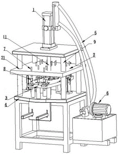
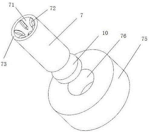
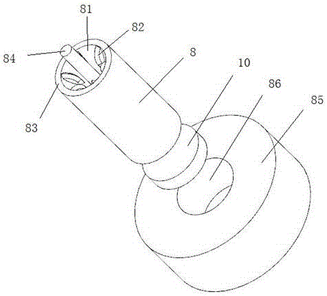
[0022] A press rivet auxiliary leveling device, such as Figure 1-Figure 4 As shown, it includes a hydraulic cylinder 1, a mounting plate 2, a mounting plate 2 3, a base 4, and a hydraulic station 6. The hydraulic cylinder 1 is connected to the hydraulic station 6 through an oil pipe 5. The hydraulic cylinder 1 has an actuator rod 11. The mounting plate one 2 is connected with the execution rod 11, and a plurality of upper punches 7 are distributed on the mounting plate one 2, and the mounting plate two 3 is installed on the base 4, and the mounting plate two 3 corresponds to the upper The punch 7 is distributed with a plurality of lower punches 8, the installation plate one 2 is located above the installation plate two 3, workpieces can be plac...


PUM


Abstract

The invention relates to an auxiliary leveling device for pressing of rivets. The auxiliary leveling device comprises a hydraulic oil cylinder, a first mounting plate, a second mounting plate and a base. The hydraulic oil cylinder is connected with a hydraulic station through an oil pipe, and the hydraulic oil cylinder is provided with an execution rod. The first mounting plate is connected with the execution rod, a plurality of upper punches are distributed on the first mounting plate, the second mounting plate is arranged on the base, and a plurality of lower punches corresponding to the upper punches are distributed on the second mounting plate. The first mounting plate is located above the second mounting plate, and a workpiece can be placed between the first mounting plate and the second mounting plate. The upper punches are arranged on the first mounting plate, and the lower punches are arranged on the corresponding second mounting plate so that stamping riveting of a plurality of rivets on one surface or in one direction can be completed in one-time stamping, the number of operators and the number of riveting machines are reduced, and the field use space is saved; and operation is easy, the labor intensity of the operators is reduced, and the production efficiency is improved.

Description

technical field [0001] The invention relates to the technical field of PCB pressing technology, in particular to an auxiliary leveling device for pressing rivets. Background technique [0002] After the PCB multi-layer board is nailed by the rivet machine, there may be problems such as uneven rivet opening or the selection of rivets that are too long to be higher than the board surface, which will easily cause poor quality problems such as copper wrinkles near the pressed rivet position; however, press The traditional method of knocking flat with an iron hammer is prone to scratching the browning layer in the unit or copper shavings falling into the unit and causing a short circuit. Existing rivet machines generally use simple punches for punching, which do not have guidance for the rivet blooming, and cannot control the uniformity and smoothness of the rivet blooming, and different circuit boards require different rivet positions, often requiring Several or even dozens of ...

Claims


Application Information

Patent Timeline
Patent Type & Authority Applications(China)
IPC IPC(8): B21J15/14B21J15/20B21J15/38B21D19/08H05K3/46
CPCB21D19/08B21J15/14B21J15/20B21J15/38H05K3/4611
Inventor 邱成伟王晓槟李小海叶汉雄
Owner HUIZHOU ZHONGJING ELECTRONICS TECH CO LTD
Learn More