Transmission device for automobile seat adjustor

A transmission device and car seat technology, which is applied to the transmission device, transmission device parts, vehicle seats, etc., can solve the problems of shortened life, overall deflection of bearing sleeves, and increased noise, so as to increase wear and improve structure Strength, performance-enhancing effects

Pending Publication Date: 2017-06-06
SUZHOU SINNOTECH ELECTRONICS TECH
View PDF11 Cites 4 Cited by
  • Summary
  • Abstract
  • Description
  • Claims
  • Application Information

AI Technical Summary

Problems solved by technology

[0003] However, the support section and the guide section are the same part that is integrally formed. During the transmission process, the screw rod and the guide section continuously rub against each other and generate a radial force on the impact. The force is directly transmitted to the support section, thereby making the The bearing sleeve produces overall deflection and vibration, and the noise becomes larger
In addition, since the above-mentioned guide section is set as an axially extending cantilever structure, the guiding strength for the screw rod is insufficient, which may cause the screw rod and the worm wheel to be obliquely matched, resulting in vibration and increased noise
On the other hand, the guide section has higher requirements on the wear resistance of the material, while the support section has higher requirements on the lubricity of the material. The material selection of the existing bearing sleeve must balance the above two requirements, and the wear resistance of the guide section will be insufficient and excessive. Early wear, resulting in increased noise and shortened life

Method used


Image

  • Transmission device for automobile seat adjustor
  • Transmission device for automobile seat adjustor
  • Transmission device for automobile seat adjustor

Examples


Embodiment Construction

[0020] The present invention will be described in detail below with reference to the embodiments shown in the accompanying drawings. However, this embodiment does not limit the present invention, and any structural, method, or functional changes made by those skilled in the art according to this embodiment are included in the protection scope of the present invention.

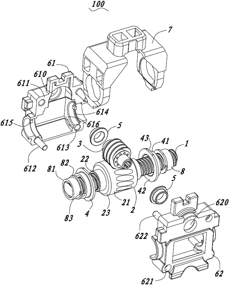
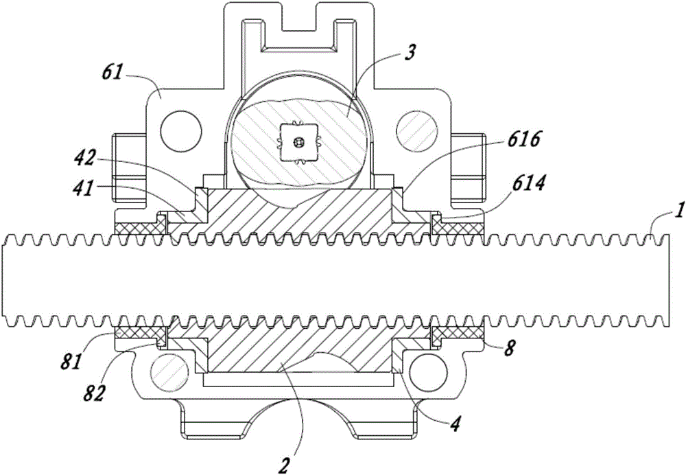
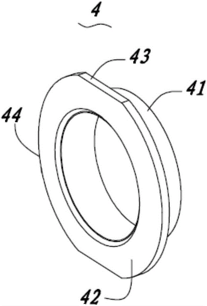
[0021] see Figure 1 to Figure 3 It is a preferred embodiment of the transmission device 100 for the car seat adjuster of the present invention. The transmission device 100 includes a screw 1, a worm wheel 2 sleeved on the screw 1, a worm 3 driving the worm wheel 2 to rotate, an output bearing 4 arranged at both ends of the worm wheel 2, an input bearing 5 arranged at both ends of the worm, and To fix the housing carrying the output bearing 4 and the input bearing 5 .

[0022] Wherein, the worm wheel 2 has an internal thread adapted to the screw 1, the worm 3 is arranged perpendicular to the worm wheel 2 and ...


PUM


Abstract

The invention provides a transmission device for an automobile seat adjustor. The transmission device for the automobile seat adjustor comprises a screw rod, a worm wheel, a worm, an output bearing, an input bearing and a housing, wherein the worm wheel is arranged on the screw rod in a sleeving way; the worm rod drives the worm wheel to rotate; the output bearing is arranged at the two ends of the worm wheel; the input bearing is arranged at the two ends of the worm; the housing is used for fixing and bearing the input bearing and the output bearing. The worm wheel is provided with an internal thread matched with the screw rod, so that the worm wheel can perform reciprocating motion along the screw rod during rotation. The transmission device also comprises a guide bearing which is arranged at the periphery of the screw rod in a sleeving way and fixed with the housing; the guide bearing, the output bearing and the worm wheel are arranged at intervals in the axial direction. Due to the adoption of the transmission device, friction vibration between the guide bearing and the screw rod is prevented from being transmitted to the worm wheel, so that inclined cooperation of the worm wheel and the screw rod, noise generation and abrasion enhancement are avoided; the structure strength of the guide bearing can be improved, and corresponding forming materials are convenient to select to meet the supporting requirement of the worm wheel and the guide requirement of the screw rod respectively.

Description

technical field [0001] The invention relates to the technical field of auto parts, in particular to a transmission device for an auto seat adjuster. Background technique [0002] Traditional car seats mostly use manual methods to adjust the front and rear position of the seat, which is inconvenient to operate. In recent years, more and more automotive products have begun to adopt electric seat adjustment devices to improve user experience. A car seat adjuster has also been disclosed in the industry, which has a screw, a reciprocating worm sheathed on the screw, and a worm that drives the worm to rotate. Chinese patent CN100443776 C discloses a transmission mechanism for an adjustment device, which includes a bearing sleeve matched with a screw nut, and the bearing sleeve has a supporting section and a guiding section. The guide section optimizes the coaxiality between the screw rod and the screw nut when the screw nut is adjusted and operated, and then achieves harmonious ...

Claims


Application Information

Patent Timeline
Patent Type & Authority Applications(China)
IPC IPC(8): B60N2/06F16H37/02F16H57/00
CPCF16H37/02F16H57/0006B60N2/067B60N2/02253
Inventor 叶茂朱锐蔡益民董建江张帅孙凯
Owner SUZHOU SINNOTECH ELECTRONICS TECH
Why Eureka
Try Eureka