Gas filed well site power supply and data acquisition transmission system and arrangement method thereof
A data acquisition and well site technology, applied in the direction of electrical signal transmission system, transmission system, signal transmission system, etc., can solve the lack of large differences in equipment layout in the cabinet, strong and weak current direction, equipment size, power supply load, etc., working interface In order to avoid problems such as unclear division, the effect of avoiding insufficient RTU points, improving design efficiency and quality, and saving I/O interfaces
- Summary
- Abstract
- Description
- Claims
- Application Information
AI Technical Summary
Benefits of technology
Problems solved by technology
Method used
Image
Examples
Embodiment 1
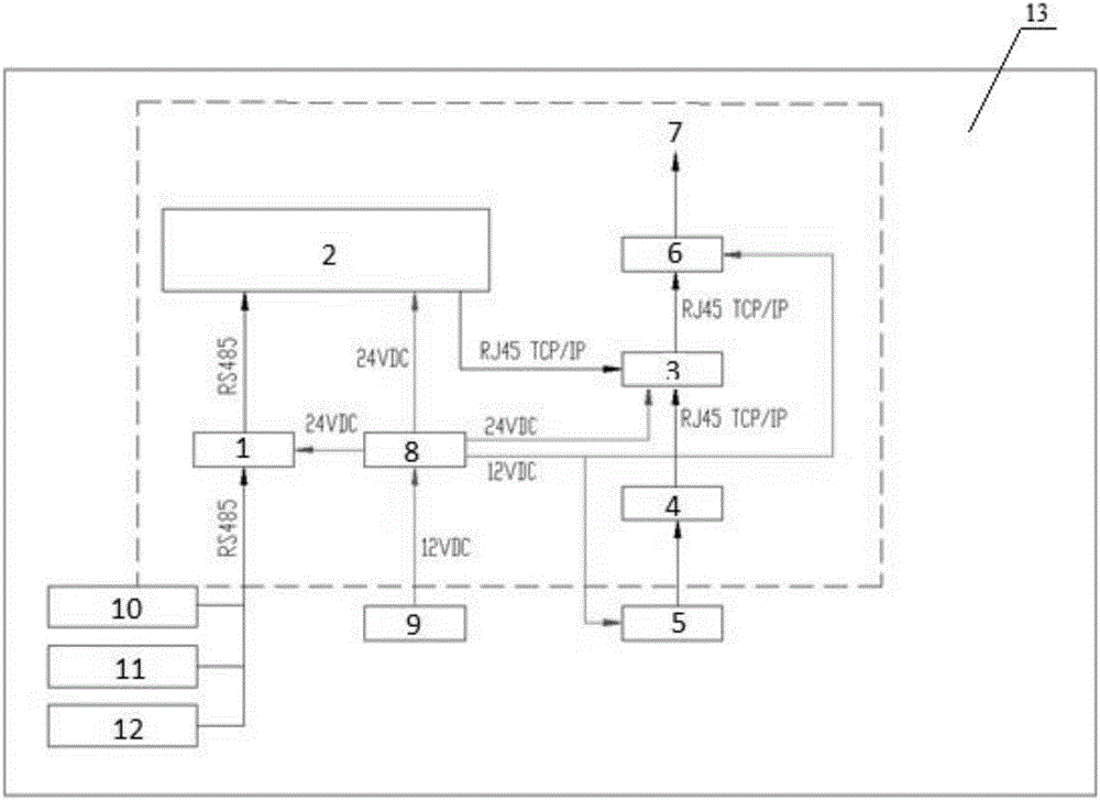
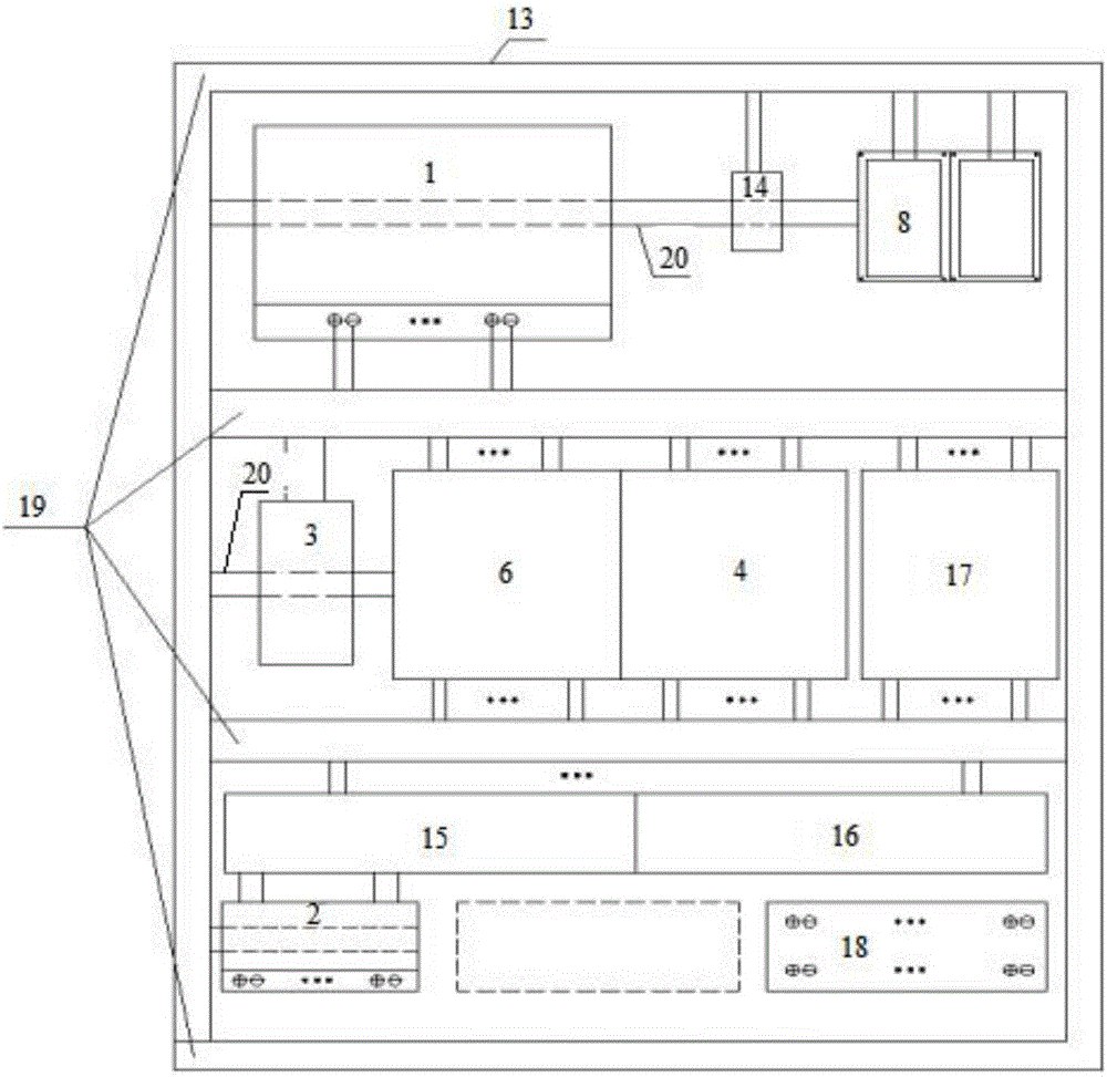
[0030] Such as figure 1 As shown, the present invention provides a gas field well site power supply and data acquisition and transmission system, including a cabinet 13, at least a hub 1, a well site RTU2, an industrial switch 3, a video server 4, and a wireless data transmission module 6 are arranged in the cabinet 13 , host computer 7 and power supply module 8, the hub 1 is used to collect well site instrument data, the signal output end of the hub 1 is connected to the well site RTU2, and the well site RTU2 and the video server 4 pass through the industrial switch 3 and the wireless data transmission module 6 communication, the wireless data transmission module 6 is connected to the upper computer 7 through a wireless network, and the power supply module 8 supplies power for the hub 1, the well site RTU2, the industrial switch 3 and the wireless data transmission module 6.
[0031] The RTU mentioned above is the abbreviation of REMOTE TERMINAL UNIT, and the wellsite RTU2 is...
Embodiment 2
[0034] On the basis of Embodiment 1, the well site RTU collects the data of the well site instrument through the hub. The well site instrument includes the well site pressure transmitter 10, the wellhead high and low pressure emergency shut-off valve 11 and the flow meter 12, etc. The well site RTU2 Through the RJ45 interface, communicate with the industrial switch 3 with the TCP / IP protocol, realize the communication with the upper computer 7 through the industrial switch 3 and the wireless data transmission module 6, and realize data acquisition control, storage, forwarding, management and control of field electrical or electronic equipment, and has the functions of lightning protection and surge protection.
[0035] The aforementioned industrial switch 3 receives the data transmitted by the well site RTU and the video server, and communicates the data with the data transmission station through the RJ45 interface through the TCP / IP protocol to realize the exchange of informat...
Embodiment 3
[0040]On the basis of the above-mentioned embodiments, the cabinet 13 is also arranged with a surge protector 15, an air switch 16, a wind-solar hybrid controller 17, a connection terminal 18, and a reserved position for a hub. The surge protector 15 And the air switch 16 is connected between the RS485 hub 1 and the well site RTU2; the terminal 18 is used for the working interface of the well site equipment and the well site RTU; Solar battery anti-reverse connection, battery overcharge, battery over-discharge, battery anti-reverse connection, load overload, short circuit protection, lightning protection, fan current limiting, fan automatic braking and manual braking and other protection functions; setting the reserved position of the hub makes the cabinet 13 With its own expansion function, the hub satisfies the expansion of well site data to the maximum extent, and avoids the problem of insufficient RTU points in the later expansion.
PUM
 Abstract
Description
Claims
Application Information
 - R&D
- Intellectual Property
- Life Sciences
- Materials
- Tech Scout
- Unparalleled Data Quality
- Higher Quality Content
- 60% Fewer Hallucinations
Browse by: Latest US Patents, China's latest patents, Technical Efficacy Thesaurus, Application Domain, Technology Topic, Popular Technical Reports.
© 2025 PatSnap. All rights reserved.Legal|Privacy policy|Modern Slavery Act Transparency Statement|Sitemap|About US| Contact US: help@patsnap.com


