
Impeller crushing machine

A pulverizer and impeller technology, applied in grain processing and other directions, can solve the problems of inability to work continuously, difficult maintenance, easy heating of the machine, etc., and achieve the effect of improving pulverization efficiency, high pulverization efficiency and low price.

Inactive Publication Date: 2017-06-09
HENGYANG SHUANGYAN TRANSPORTATION MACHINERY
View PDF10 Cites 0 Cited by
  • Summary
  • Abstract
  • Description
  • Claims
  • Application Information

AI Technical Summary

Problems solved by technology

[0002] At present, the existing pulverizers used in feed, medicine, food, agricultural production and other industries cannot directly pulverize materials with high water content during the pulverization process, and need to be dried or dried first, resulting in low output and poor pulverization effect. It is very prone to machine blockage, the machine is prone to heat, cannot work continuously, cannot be factory-operated, requires many workers, cannot meet the requirements of large-scale production, and can only meet family workshop production
Most of the existing large-scale factory-operated pulverizers have complex structures and are difficult to maintain, and most of them adopt the reciprocating hammering mode, and the efficiency in the working process is not high
Because the crushing operation has very high requirements on equipment, most of the traditional grinders use special steel, which makes the price of the grinder very high.

Method used


Image

  • Impeller crushing machine
  • Impeller crushing machine
  • Impeller crushing machine

Examples


Embodiment

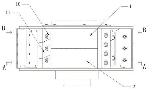
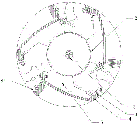
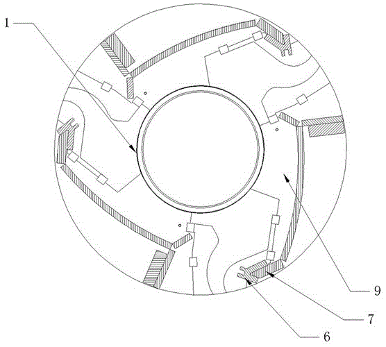
[0021] Such as Figure 1-Figure 3 The shown impeller pulverizer includes an impeller assembly and a main shaft; the impeller assembly includes an upper impeller and a lower impeller, and the main shaft includes a primary main shaft 1 and a secondary main shaft 2; the upper impeller and the primary main shaft 1 are connected through an expansion sleeve, and the lower impeller It is connected with the secondary main shaft 2 through an expansion sleeve, and the rotation directions of the primary main shaft 1 and the secondary main shaft 2 are opposite; the lower end of the secondary main shaft 2 is provided with a material distribution cone 3, which is in the shape of a trapezoidal cylinder; There are 3 crushing blades evenly arranged, and the crushing blades include the lower throwing head 4, the wear-resistant baffle 8 and the lower connecting arm 5; one end of the lower connecting arm 5 is connected to the primary spindle 1, and the other end is connected to the lower throwing ...


PUM


Abstract

The invention discloses an impeller crushing machine. The impeller crushing machine comprises an impeller assembly and main shafts, wherein the impeller assembly comprises an upper impeller and an lower impeller, and the main shafts comprise a first-stage main shaft and a second-stage main shaft; the upper impeller is connected with the first-stage main shaft through an expansion sleeve, the lower impeller is connected with the second-stage main shaft through an expansion sleeve, and the rotation direction of the first-stage main shaft is opposite to the rotation direction of the second-stage main shaft; a material distributing cone is arranged at the lower end of the second-stage main shaft, and the material distributing cone is in a trapezoid cylinder shape; three crushing blades are uniformly arranged on the lower impeller, wherein each crushing blade comprises a lower throwing head, a wear-resistant baffle and a lower connecting arm; and one end of each lower connecting arm is connected to the first-stage main shaft, the other end of each lower connecting arm is connected with the corresponding lower throwing head, and each wear-resistant baffle is connected to the corresponding lower connecting arm through bolts. The impeller crushing machine has the advantages of being simple in structure, high in crushing efficiency and low in price.

Description

technical field [0001] The invention relates to a pulverizer, in particular to an impeller pulverizer. Background technique [0002] At present, the existing pulverizers used in feed, medicine, food, agricultural production and other industries cannot directly pulverize materials with high water content during the pulverization process, and need to be dried or dried first, resulting in low output and poor pulverization effect. It is very prone to machine blockage, the machine is prone to heat, cannot work continuously, cannot be factory-operated, requires many workers, cannot meet the requirements of large-scale production, and can only meet family workshop production. Most of the existing large-scale factory-operated pulverizers have complex structures and are difficult to maintain, and most of them adopt the reciprocating hammering mode, and the efficiency in the working process is not high. Because the crushing operation has very high requirements on the equipment, most ...

Claims


Application Information

Patent Timeline
IPC IPC(8): B02C13/20B02C13/14B02C13/26B02C13/286
CPCB02C13/205B02C13/14B02C13/26B02C13/286B02C2013/145B02C2013/28618
Inventor 伍增产范涛
Owner HENGYANG SHUANGYAN TRANSPORTATION MACHINERY
Learn More