Thin-wall ring part machining method and automatic auxiliary supporting device thereof

A technology for auxiliary support and processing methods, applied in positioning devices, metal processing equipment, metal processing machinery parts, etc., can solve the problem of low degree of automation, no comprehensive consideration of workpiece deformation release and wall thickness requirements, weak rigidity of thin-walled ring parts, etc. problems, achieve high precision, small processing deformation, and improve flexibility

Active Publication Date: 2017-06-09
NANJING UNIV OF AERONAUTICS & ASTRONAUTICS
View PDF9 Cites 30 Cited by
  • Summary
  • Abstract
  • Description
  • Claims
  • Application Information

AI Technical Summary

Problems solved by technology

[0004] The purpose of the present invention is to aim at the existing auxiliary supporting device for thin-walled annular parts. Although the problem of weak rigidity of thin-walled annular parts is generally solved, it does not comprehensively consider the problems of workpiece deformatio...

Method used


Image

  • Thin-wall ring part machining method and automatic auxiliary supporting device thereof
  • Thin-wall ring part machining method and automatic auxiliary supporting device thereof
  • Thin-wall ring part machining method and automatic auxiliary supporting device thereof

Examples


Embodiment 1

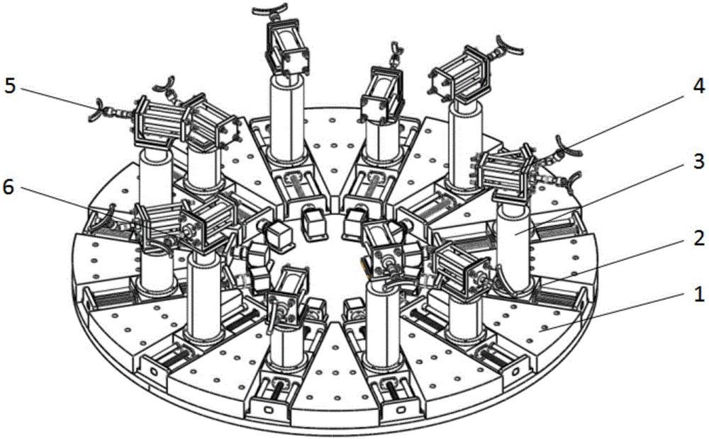
[0032] Such as figure 1 .

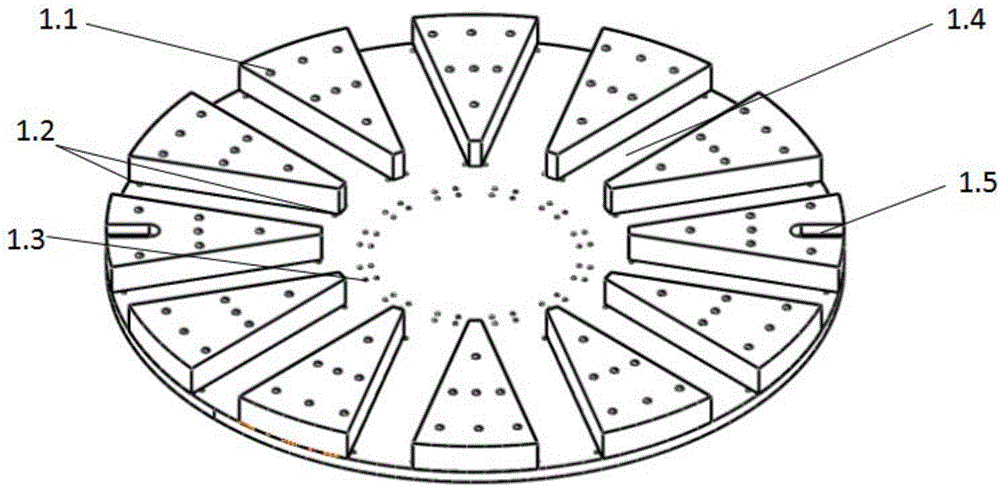
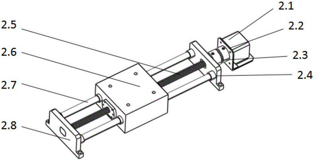
[0033] An automatic auxiliary support device for processing thin-walled ring parts, which includes: a base 1 ( figure 2 ), transmission mechanism 2 ( image 3 ), Z-direction lifting platform 3 (such as Figure 4 ), radial auxiliary support 4 ( Figure 5 ), force sensor 5 and distance sensor 6, its assembly diagram is as follows figure 1 As shown; the base 1 is a ring-shaped fixture main body installation platform, which is connected with the machine tool workbench through screws and pressure plates. The base 1 is provided with a positioning notch 1.5 for positioning when installing thin-walled ring parts and multiple uniformly distributed for installation The installation groove 1.4 of the transmission mechanism 2; the transmission mechanism 2 is radially installed in the installation groove 1.4 of the base 1 and can move radially in the installation groove 1.4 to realize the radial position adjustment of the radial auxiliary support 4; the Z-dir...

Embodiment 2

[0036] A method for processing a thin-walled ring, the specific implementation of which is as follows: Figure 7 The thin-walled annular part 7 shown is a casing of an aero-engine combustion chamber. When processing this part, the blank is firstly fixed on the base of the automatic auxiliary support device through the positioning of the seam and the pressing of the pressure plate, and the movement of each transmission mechanism is controlled. At D=300mm, rough machining is carried out on the inner surface of the blank, such as Figure 8 As shown, at this time the workpiece support surface machining allowance a = 5mm. The distance L between the workpiece support surface and each radial auxiliary support fixed bracket is measured by the distance sensor on the automatic auxiliary support device, and the difference between the measured maximum and minimum values ​​ΔL=0.5mm is less than the machining allowance a of the support surface, and each control The radial auxiliary support...


PUM


Abstract

The invention discloses a thin-wall ring part machining method and an automatic auxiliary supporting device thereof. According to the allowance of a workpiece bearing surface, the corresponding machining method can be adopted. In the manufacturing procedure that the workpiece bearing surface has allowance, according to the change of contact force between the workpiece bearing surface and the automatic auxiliary supporting device after a certain number of materials of workpieces are removed, the automatic auxiliary supporting device can automatically adjust radial auxiliary supporting space positions, and workpiece deformation in the machining process can be released. In the manufacturing procedure that the workpiece bearing surface does not have allowance, the automatic auxiliary supporting device is controlled to support the workpiece bearing surface to be of an ideal shape, and then machining is performed. In order to implement the machining method, the automatic auxiliary supporting device is invented, and the device can adjust the radial auxiliary supporting space positions automatically. By means of the thin-wall ring part machining method and the automatic auxiliary supporting device thereof, the effect that part deformation is small after unloading is guaranteed, wall thickness precision can meet the requirements, and meanwhile automation of the auxiliary supporting device is realized.

Description

technical field [0001] The invention relates to a mechanical processing technology, in particular to a thin-walled annular piece processing method and its automatic auxiliary support device, which adopts a corresponding processing strategy according to the supporting surface margin of the workpiece, in particular to a thin-walled annular piece processing method and its automatic auxiliary support device. Background technique [0002] Thin-walled ring parts are widely used in the aerospace field because of their light weight and high structural efficiency. However, most thin-walled ring parts have complex structures, thin walls and poor rigidity, and are prone to instability and vibration during processing. Therefore, it is necessary to apply auxiliary supports to weakly rigid parts to increase the rigidity of the workpiece. However, in the process of processing, although the auxiliary support improves the rigidity of the workpiece, it limits the release of the deformation o...

Claims


Application Information

Patent Timeline
IPC IPC(8): B23Q3/06
CPCB23Q3/065
Inventor 郝小忠李迎光刘旭刘长青程浩
Owner NANJING UNIV OF AERONAUTICS & ASTRONAUTICS
Why Eureka
Try Eureka