
Portable Cylinder Pneumatic Marking Machine

A portable, steel cylinder technology, applied in typewriters, printing, etc., can solve the problems of difficult reference positioning and printing failure, and achieve the effect of reasonable structure, ingenious design, and convenient use

Active Publication Date: 2019-05-03
重庆初刻智能机械设备有限公司
View PDF5 Cites 0 Cited by
  • Summary
  • Abstract
  • Description
  • Claims
  • Application Information

AI Technical Summary

Problems solved by technology

At present, due to the large size of the steel cylinder and the large shoulder surface of the steel cylinder, the steel cylinder is not suitable for marking on the desktop pneumatic marking machine. However, if the portable pneumatic marking machine is used for marking, the benchmark positioning of the ordinary portable pneumatic marking machine It is difficult, and the short-stroke pneumatic marking head of the existing portable pneumatic marking machine cannot print

Method used


Image

  • Portable Cylinder Pneumatic Marking Machine
  • Portable Cylinder Pneumatic Marking Machine
  • Portable Cylinder Pneumatic Marking Machine

Examples


Embodiment 1

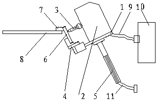
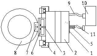
[0022] refer to figure 1 , figure 2 , image 3 , a portable pneumatic marking machine for steel cylinders, a handle 5 is fixed vertically on the back of the vertical support 1, a marking head driver 2 is fixed on the front of the vertical support 1, and a horizontal support 4 is fixed on the bottom of the vertical support 1 , a marking frame 6 is fixedly installed on the horizontal support 4, a steel cylinder collar connecting block 7 is arranged on the marking frame 6, and a steel cylinder collar 8 and a cable 9 are fixed on the steel cylinder collar connecting block 7 with connectors One end of the cable 9 is connected to the marking head translation drive system in the marking head driver 2, the other end of the cable 9 is connected to the computer control box 10, one end of the air pipe 11 is connected to the compressed air source, and the other end of the air pipe 11 is connected to the marking head driver. The pneumatic system in 2 is connected, and the long-stroke pn...

Embodiment 2

[0024] refer to figure 1 , figure 2 , image 3 , a portable pneumatic marking machine for steel cylinders, a handle 5 is fixed vertically on the back of the vertical support 1, a marking head driver 2 is fixed on the front of the vertical support 1, and a horizontal support 4 is fixed on the bottom of the vertical support 1 , a marking frame 6 is fixedly installed on the horizontal support 4, a steel cylinder collar connecting block 7 is arranged on the marking frame 6, and a steel cylinder collar 8 and a cable 9 are fixed on the steel cylinder collar connecting block 7 with connectors One end of the cable 9 is connected to the marking head translation drive system in the marking head driver 2, the other end of the cable 9 is connected to the computer control box 10, one end of the air pipe 11 is connected to the compressed air source, and the other end of the air pipe 11 is connected to the marking head driver. The pneumatic system in 2 is connected, and the long-stroke pn...

Embodiment 3

[0026] refer to figure 1 , figure 2 , image 3 , a portable pneumatic marking machine for steel cylinders, a handle 5 is fixed vertically on the back of the vertical support 1, a marking head driver 2 is fixed on the front of the vertical support 1, and a horizontal support 4 is fixed on the bottom of the vertical support 1 , a marking frame 6 is fixedly installed on the horizontal support 4, a steel cylinder collar connecting block 7 is arranged on the marking frame 6, and a steel cylinder collar 8 and a cable 9 are fixed on the steel cylinder collar connecting block 7 with connectors One end of the cable 9 is connected to the marking head translation drive system in the marking head driver 2, the other end of the cable 9 is connected to the computer control box 10, one end of the air pipe 11 is connected to the compressed air source, and the other end of the air pipe 11 is connected to the marking head driver. The pneumatic system in 2 is connected, and the long-stroke pn...


PUM


Abstract

The invention relates to a portable steel cylinder pneumatic marking machine. In the portable steel cylinder pneumatic marking machine, the back surface of a longitudinal support is fixedly vertically provided with a handle, the front surface of the longitudinal support is fixedly provided with a marking head driver, the lower part of the longitudinal support is fixedly provided with a horizontal support, the horizontal support is fixedly provided with a marking frame, the marking frame is provided with a steel cylinder collar connection block, the steel cylinder collar connection block is fixedly provided with a steel cylinder collar with a connection piece, one end of a cable is connected with a marking head translation driving system in the marking head driver, the other end of the cable is connected with a computer control box, one end of a gas pipe is connected with a compression air source, the other end of the gas pipe is connected with a pneumatic system in the marking head driver, and a long-stroke pneumatic marking head can move in the marking frame. The pneumatic marking machine is advantaged by reasonable structure, smart design, convenient usage and long service life, can meet marking requirements of various steel cylinders, and has a popularization value.

Description

technical field [0001] The present invention relates to a portable pneumatic marking machine, more specifically to a portable pneumatic marking machine for steel cylinders. Background technique [0002] Pneumatic marking machine is a mechanical device that prints by impacting the printing needle with compressed air. Pneumatic marking machines are generally divided into two categories, one is desktop pneumatic marking machines, and the other is portable pneumatic marking machines. Pneumatic marking machine is mainly composed of four parts: first, computer hardware and special software; second, drive control system; third, pneumatic system; fourth, marking workbench. The working principle of the pneumatic marking machine is to input the information such as graphics and text to be marked into the computer, and the computer controls the drive system and pneumatic system through a special control board. The industrial-grade X-Y scanning system carries the marking head movement a...

Claims


Application Information

Patent Timeline
Patent Type & Authority Patents(China)
IPC IPC(8): B41J2/225B41J3/407B41J3/413
CPCB41J2/225B41J3/4073B41J3/413
Inventor 陶道忠肖仁敏
Owner 重庆初刻智能机械设备有限公司
Learn More