
Semiconductor structure laser lift-off method

A laser lift-off and semiconductor technology, used in semiconductor/solid-state device manufacturing, laser welding equipment, electrical components, etc., can solve the problems of panel packaging difficulties, lower yield, and lower yield, to improve product yield and improve stability. Sex, avoid the effect of bubbles

Active Publication Date: 2017-06-09
EVERDISPLAY OPTRONICS (SHANGHAI) CO LTD
View PDF6 Cites 3 Cited by
  • Summary
  • Abstract
  • Description
  • Claims
  • Application Information

AI Technical Summary

Problems solved by technology

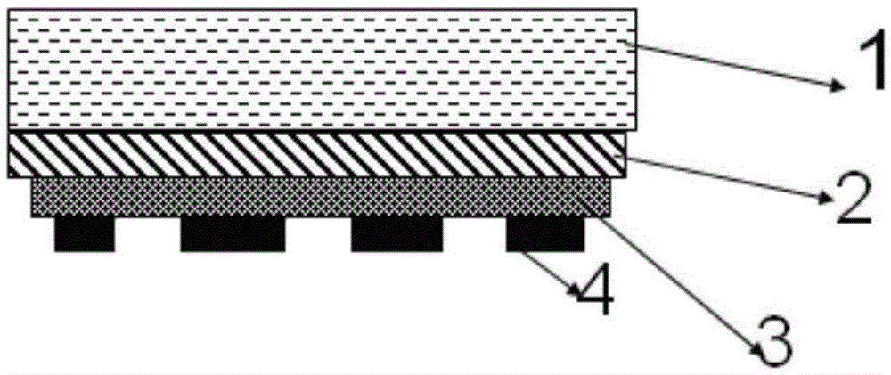
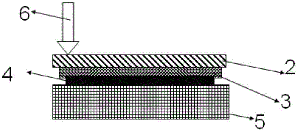
This method is simpler to package a full-size panel, such as Figure 2a shown, but it is more difficult to provide packages with external bonding points 4' strip or single size panel, such as Figure 2b As shown, when the strip-shaped or single-size panel is transferred to the carrier platform 5 placed on the laser lift-off equipment, because the strip-shaped or single-size panel is provided with external bonding points 4', between a plurality of external bonding points 4' There is a gap, which makes the panel not completely flat (point contact between the panel and the carrier platform, uneven force on the bottom of the panel, and then uneven surface) is set on the carrier platform 5, which in turn causes the laser device to be peeled off. The phenomenon of laser laser instability occurs, resulting in a decline in yield. In addition, due to the uneven surface of the polyimide film layer 3, when the supporting film 7 is attached, bubbles are easily formed on the surface of the supporting film, resulting in the sticking of the supporting film. Decreased stability, resulting in reduced yield

Method used


Image

  • Semiconductor structure laser lift-off method
  • Semiconductor structure laser lift-off method
  • Semiconductor structure laser lift-off method

Examples


specific Embodiment approach

[0048] Enumerate a specific embodiment: such as Figure 3a-3d As shown, a semiconductor structure laser lift-off process, wherein: comprising the following steps:

[0049] A large plate glass substrate 10 is provided, and a polyimide film and packaging film layer 20 are sequentially deposited on the large plate glass substrate;

[0050] The large glass substrate 10 prepared with the polyimide film and the encapsulation film 20 on the surface is placed on a second working platform;

[0051] Attaching a sub-substrate-sized encapsulation film 10 on the surface of the water and oxygen blocking film 30 to form the semiconductor structure with an uneven surface;

[0052] A plurality of protruding mechanisms 60 are fixedly arranged on the working surface 51 of the first working platform 50;

[0053] The semiconductor structure is placed on the first working platform 50, and the plurality of protrusion mechanisms 60 provided on the first working platform 10 fit with the uneven lower...


PUM


Abstract

The invention relates to the technical field of semiconductor manufacturing, and in particular to a laser lift-off method for semiconductor structures. A predetermined medium is deposited on the surface of the platform in the region matching the gap of the external bonding point to form a filling region, and a filling region is deposited sequentially. The polyimide encapsulation film layer and the substrate of the external bonding points are placed on the platform, so that the external bonding points are bonded into the filling area; the gaps between the external bonding points are filled with a predetermined medium, which can be flattened Placed on the platform, the surface of the substrate is in the same horizontal position, the accuracy of removing the substrate is improved, and because the surface of the polyimide film layer is flat, when the supporting film is attached, air bubbles are avoided, and the supporting film is improved. Attached stability, improve product yield.

Description

technical field [0001] The invention relates to the technical field of semiconductor manufacturing, in particular to a semiconductor structure laser lift-off method. Background technique [0002] In the current barrier layer attachment process, if it is a long strip or a single-panel-sized barrier layer aggregate, the large glass plate is first cut into small module panels and then removed and peeled off by laser; however, because of this The method requires more manpower and laser equipment in the module segment, so the use of large-plate laser equipment can not only reduce equipment and labor costs, but also improve the efficiency of the production line. [0003] The existing large plate laser lift-off process based on laser lift-off technology is realized through the following technical solutions. [0004] Such as Figure 1a~1c As shown, the existing large plate laser lift-off process is as follows, such as Figure 1a As shown, the large plate glass 2 and the polyimide ...

Claims


Application Information

Patent Timeline
IPC IPC(8): H01L21/50H01L21/56B23K26/00
CPCH01L21/50B23K26/00H01L21/56H01L21/565H01L21/568
Inventor 吴正伟
Owner EVERDISPLAY OPTRONICS (SHANGHAI) CO LTD
Learn More