Passive wavelength-division mobile forward network system
A network system and pre-movement technology, applied in the field of passive wavelength division mobile fronthaul network systems, can solve problems such as difficulty in detecting branch link conditions of wavelength division devices, and achieve the effects of low cost, simple operation, and small changes.
- Summary
- Abstract
- Description
- Claims
- Application Information
AI Technical Summary
Problems solved by technology
Method used
Image
Examples
no. 1 example
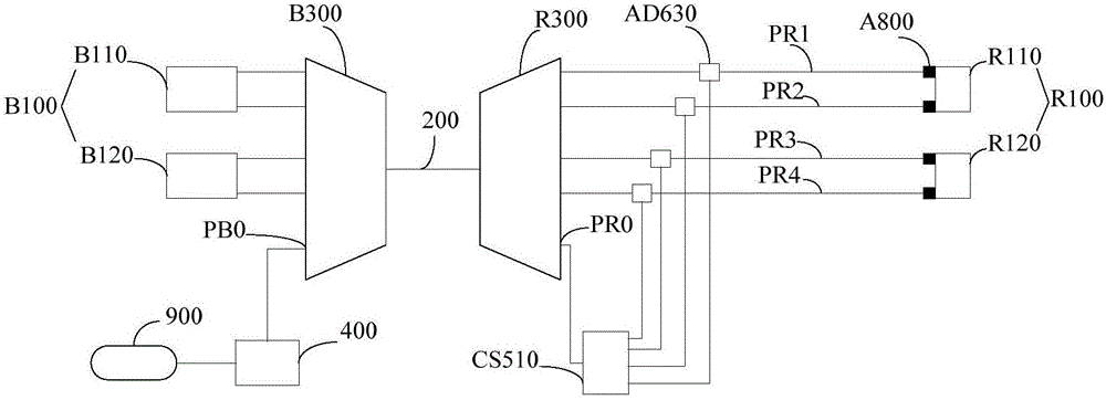
[0035] refer to figure 1 , the passive WDM mobile fronthaul network system in this embodiment includes the central office B100, the remote R100, the trunk optical fiber 200, the central office wavelength division multiplexer B300 and the remote wavelength division multiplexer R300, and the central office B100 is Refers to the communication equipment BBU, and the remote R100 refers to the communication equipment RRU. In this embodiment, there are two BBUs and two RRUs of the communication devices, respectively B110 and B120, R110 and R120. The communication equipment BBU and RRU have their own network management (not shown in the figure), and the network management can provide a limited range of alarms when some faults occur in the network.
[0036] The communication device BBU and RRU are used to send and receive communication signals to each other. Specifically, by configuring the optical modules on the BBU and RRU, the communication device B110 sends a 1310nm signal light t...
no. 2 example
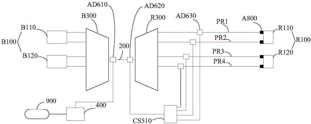
[0057] refer to figure 2 The difference between this embodiment and the first embodiment is that a first add-drop multiplexer AD610 is installed at a position close to the central office wavelength division multiplexer B300 on the trunk optical fiber 200, and a first add-drop multiplexer AD610 is installed on the trunk optical fiber 200 near the far A second add / drop multiplexer AD620 is installed at the position of the terminal wavelength division multiplexer R300.
[0058] The detection light emitted by the optical time domain reflectometer 400 enters the first add-drop multiplexer AD610 and is multiplexed with the signal light output by the central office wavelength division multiplexer B300 , and propagates on the trunk optical fiber 200 . The second add / drop multiplexer AD620 demultiplexes the detection light from the trunk optical fiber 200 and sends it to the first splitter CS510. Then, the detection light is transmitted to each branch. In this embodiment, the first ...
no. 3 example
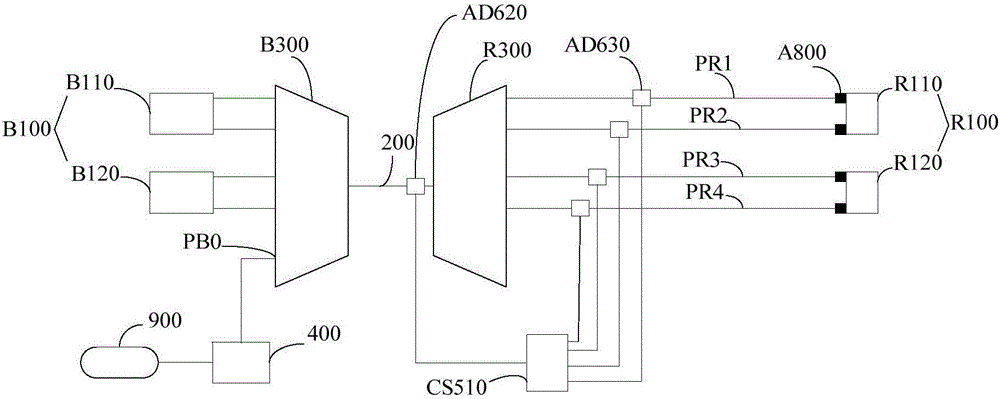
[0063] refer to image 3 The difference between this embodiment and the first embodiment is that a second add / drop multiplexer AD620 is installed at a position where the trunk optical fiber 200 is close to the remote wavelength division multiplexer R300. The second add / drop multiplexer AD620 demultiplexes the detection light from the trunk optical fiber 200 and sends it to the first splitter CS510. Then, the detection light is transmitted to each branch. In this embodiment, the first splitter CS510 is a power splitter.
[0064] In this embodiment, the central office wavelength division multiplexer B300 is the first wavelength division multiplexing device, the remote wavelength division multiplexer R300 and the second add-drop multiplexer AD620 constitute the second wavelength division multiplexing device, and the second wavelength division multiplexing device A splitter CS510 and a third add / drop multiplexer AD630 constitute an optical transmission unit.
[0065] It can be ...
PUM
 Abstract
Description
Claims
Application Information
 - R&D
- Intellectual Property
- Life Sciences
- Materials
- Tech Scout
- Unparalleled Data Quality
- Higher Quality Content
- 60% Fewer Hallucinations
Browse by: Latest US Patents, China's latest patents, Technical Efficacy Thesaurus, Application Domain, Technology Topic, Popular Technical Reports.
© 2025 PatSnap. All rights reserved.Legal|Privacy policy|Modern Slavery Act Transparency Statement|Sitemap|About US| Contact US: help@patsnap.com


