Heat dissipation device in electrical cabinet

A heat dissipation device and electrical cabinet technology, which is applied in the direction of electrical components, electrical equipment structural parts, cooling/ventilation/heating transformation, etc., can solve problems such as electricity accidents, affect the life and reliability of motors, and damage components, and achieve promotion Efficient effect of gas flow and cooling effect

Active Publication Date: 2017-06-09
STATE GRID CORP OF CHINA +2
View PDF4 Cites 1 Cited by
  • Summary
  • Abstract
  • Description
  • Claims
  • Application Information

AI Technical Summary

Problems solved by technology

[0002] The electrical cabinet is made of steel and used to protect the normal operation of components. With the advancement of technology, more and more electronic devices are installed in the electrical cabinet, and the heat generated is also increasing. This makes the heat dissipation The motor of the fan needs to work with high load for a long time, and the motor itself will generate a lot of heat when it is working. Working at a high temperature will affect the life and reliability of the motor. Once the motor is damaged or fails, it will affect the electrical cabinet. Devices, these devices may be damaged due to high temperature, causing electricity accidents and posing safety hazards

Method used


Image

  • Heat dissipation device in electrical cabinet
  • Heat dissipation device in electrical cabinet

Examples


Embodiment Construction

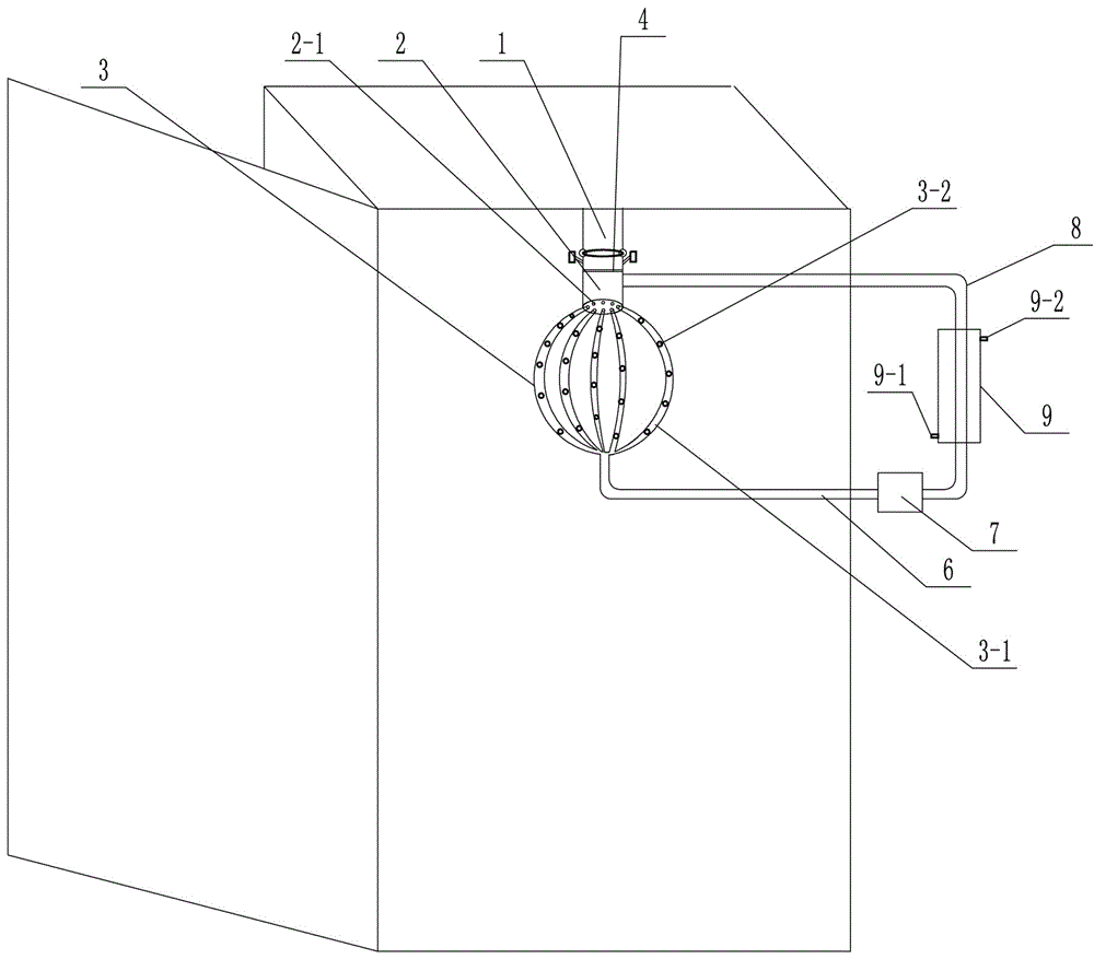
[0016] The invention includes a fixed pipe 1, a connecting pipe 2, a heat dissipation ball 3 and a gas circulation pipeline.

[0017] The top of the fixed pipe 1 is affixed to the top plate in the electrical cabinet, the bottom of the fixed pipe 1 is twisted with the top of the connecting pipe 2, and the connecting pipe 2 is provided with a partition 4, preferably , the partition plate 4 is located on the upper part of the connecting pipe 2, and the bottom of the connecting pipe 2 is uniformly provided with ventilation holes 2-1, and the ventilation holes 2-1 are evenly distributed on the floor plane at the bottom of the connecting pipe 2, the The heat dissipation ball 3 is located below the connecting pipe 2, and the heat dissipation ball 3 includes 3-20 arc-shaped heat dissipation pipes 3-1, and the heat dissipation pipes 3-1 are provided with heat dissipation holes 3-2, and the heat dissipation holes 3 -2 is uniformly dispersed on the outer surface of the heat dissipation p...


PUM


Abstract

The invention relates to a heat dissipation device in an electrical cabinet. The heat dissipation device comprises a fixing pipe, a connecting pipe, a heat dissipation ball, and a gas circulation pipeline. The top end of the fixing pipe is fixedly connected with the top plate in the electrical cabinet, and a clapboard is disposed in the connecting pipe. The bottom plate of the bottom part of the connecting pipe is uniformly provided with air vent holes, and the heat dissipation ball comprises 3-20 arc-shaped heat dissipation pipes. The heat dissipation pipes are provided with heat dissipation holes, and the bottom parts of the heat dissipation pipes in the heat dissipation ball are merged together. The gas circulation pipeline comprises an air exhaust pipe, an air pump, and an air feeding pipe. The connecting pipe is provided with a connecting pipe adjusting device, which comprises a cabinet fixing plate, a first connecting rod, a second connecting rod, a third connecting rod, and a spring. The heat dissipation device has advantages of good heat dissipation effect, simple and flexible structure.

Description

technical field [0001] The invention relates to the field of electric equipment, in particular to a heat dissipation device in an electric cabinet. Background technique [0002] The electrical cabinet is made of steel and used to protect the normal operation of components. With the advancement of technology, more and more electronic devices are installed in the electrical cabinet, and the heat generated is also increasing. This makes the heat dissipation The motor of the fan needs to work with high load for a long time, and the motor itself will generate a lot of heat when it is working. Working at a high temperature will affect the life and reliability of the motor. Once the motor is damaged or fails, it will affect the electrical cabinet. Devices, these devices may be damaged due to high temperature, causing electricity accidents and posing safety hazards. Contents of the invention [0003] The technical problem to be solved by the present invention is to provide a heat...

Claims


Application Information

Patent Timeline
Patent Type & Authority Applications(China)
IPC IPC(8): H05K7/20
CPCH05K7/20145H05K7/20218Y02D10/00
Inventor 耿彦波张惠君董天玉周怀华张伟霞
Owner STATE GRID CORP OF CHINA
Why Eureka
Try Eureka