A high-efficiency and energy-saving rigid-flexible mixing impeller

A high-efficiency, energy-saving, stirring paddle technology, applied to mixers with rotating stirring devices, mixers, dissolving, etc., can solve the problem of "dead zone" of stirring, and achieve the goal of increasing turbulence, improving mixing efficiency, and strengthening the transfer process Effect

Active Publication Date: 2019-10-11
CHONGQING UNIV
View PDF2 Cites 0 Cited by
  • Summary
  • Abstract
  • Description
  • Claims
  • Application Information

AI Technical Summary

Problems solved by technology

People often adopt the method of increasing the rotating speed to improve the mixing uniformity of the material, but excessive stirring can make the fluid in the stirring tank move in a circular motion, and it is easy to appear a stirring "dead zone".

Method used


Image

  • A high-efficiency and energy-saving rigid-flexible mixing impeller
  • A high-efficiency and energy-saving rigid-flexible mixing impeller
  • A high-efficiency and energy-saving rigid-flexible mixing impeller

Examples


Embodiment 1

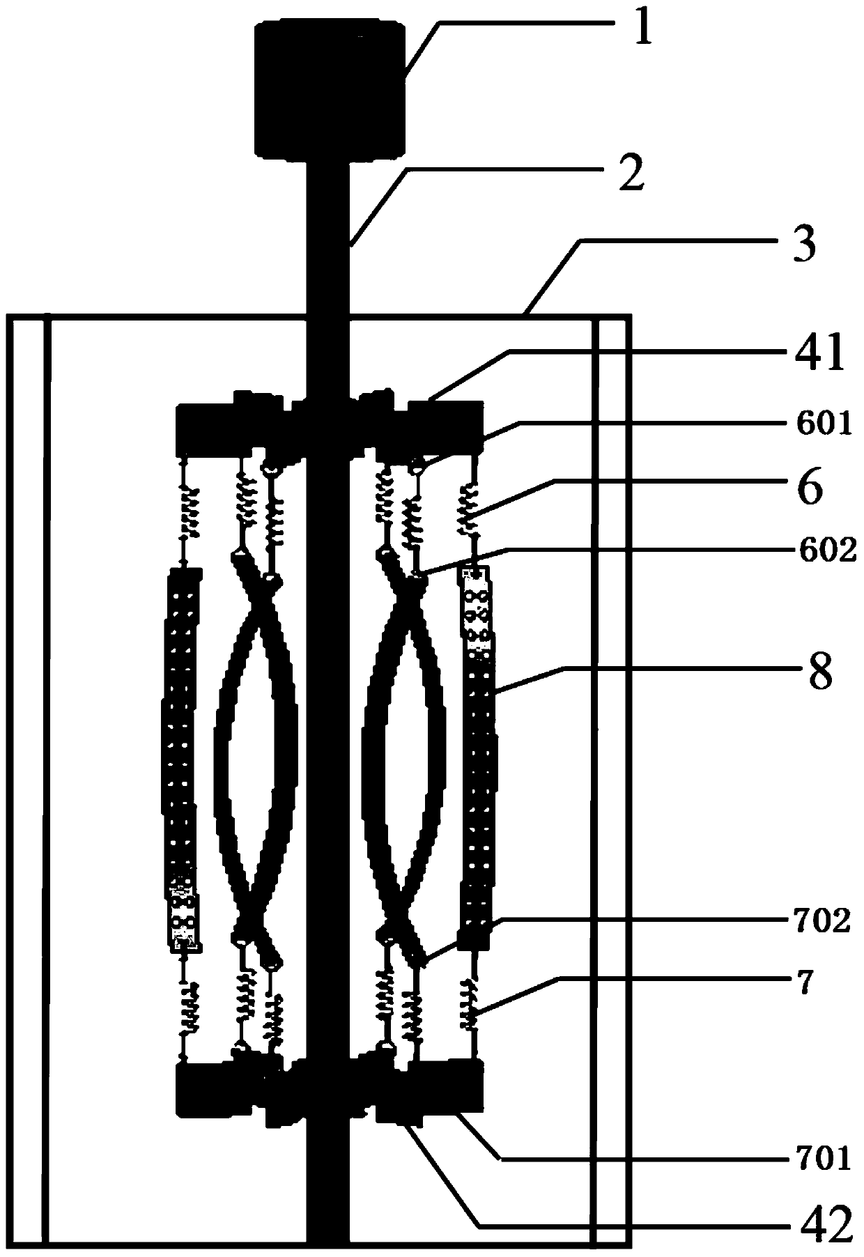
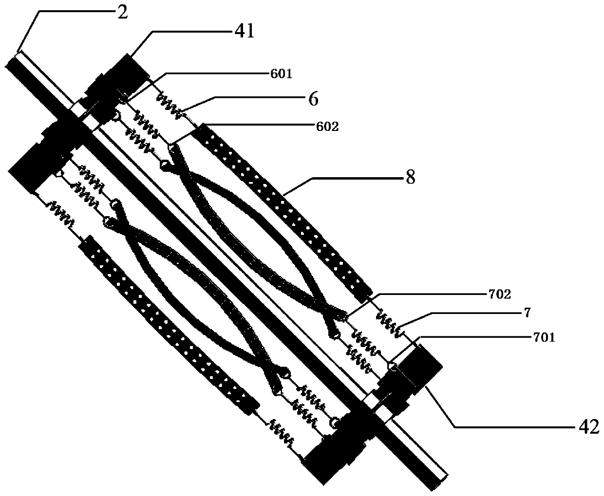
[0024] A high-efficiency and energy-saving rigid-flexible mixing paddle is characterized in that it includes a stirring shaft 2, a number of rigid paddles I41, rigid paddles II42, springs I6, springs II7 and perforated flexible sheets 8.

[0025] There are two nodes on the stirring shaft 2 . One of the nodes is connected with several rigid stirring blades I41, and these rigid stirring blades I41 form a rigid stirring blade I. Another node connects several rigid stirring blades II 42, and these rigid stirring blades II 42 form a rigid stirring blade II.

[0026] All the rigid stirring blades I41 are radially distributed around the stirring shaft 2 . The end of each rigid stirring paddle I41 is processed with a through hole, and a mounting ring I601 is passed through the through hole. A spring I6 is hung on each mounting ring I601, the spring I6 is a coil spring, and the metal rod at one end of the coil spring is bent into a hook shape (or ring shape); the spring I6 passes thr...

Embodiment 2

[0039] The main structure of this embodiment is the same as embodiment 1, further:

[0040] The diameters of the rigid stirring paddle I41 and the rigid stirring paddle II42 are equal. The paddle of rigid paddle I41 is the same size as the paddle of rigid paddle II42.

[0041] The width of the perforated flexible sheet 8 is 1 / 40-1 / 10 of the diameter D of the rigid paddle II42. It has been found through research that when the width of the perforated flexible sheet 8 is too narrow, it is beneficial for the perforated flexible sheet 8 to twist or shake, but the ability to transfer energy is poor; when the width of the perforated flexible sheet 8 is too wide, it is not conducive to Twisting or shaking, but the ability to transmit energy is strong. The width of the perforated flexible sheet 8 is d, and when d is 1 / 40-1 / 10 of D, the system can obtain a better mixing effect.

[0042] Further speaking, the distance between the lower edge of the blade of the rigid paddle I41 and the...


PUM


Abstract

The invention provides a high-efficiency energy-saving rigid-flexible combined stirring paddle, which is characterized in that it comprises a stirring shaft, a rigid paddle I, a rigid paddle II, a spring and a perforated flexible sheet. There are two nodes on the stirring shaft. One of the nodes is connected to the rigid impeller I, and the other node is connected to the rigid impeller II. A perforated flexible sheet is connected between the rigid paddle I and the rigid paddle II, and the two ends of the perforated flexible sheet in the length direction are connected to the rigid paddle I and the rigid paddle II through a spring transition. The technical effect of the present invention is unquestionable. During the rotation of the paddle, the energy consumption of the blade is reduced, and the perforated flexible sheet can perform multi-body movement, and many high-speed jets can be generated during the movement of the perforated flexible sheet, increasing the The velocity gradient of the fluid increases the degree of turbulence of the fluid, increases the energy utilization rate of the paddle, and improves the mixing efficiency of the fluid. Moreover, the cost of the stirring device can also be saved.

Description

technical field [0001] The invention relates to a fluid mixing device in the production processes of chemical industry, petrochemical industry, light industry, medicine, metallurgy, water treatment, etc., in particular to a high-efficiency energy-saving rigid-flexible combined stirring paddle. Background technique [0002] Mechanically stirred reactors are widely used in chemical, petrochemical, light industry, pharmaceutical, metallurgy, water treatment and other industries. quality and increase production efficiency. As one of the important core components of the stirred reactor, the stirring paddle can give the fluid the required appropriate energy, thereby promoting the evolution, formation, displacement of the multi-scale structure of the flow field and the transfer of energy and matter between the multi-scale flow field structures. However, less than 5% of the total mechanical input of the stirred reactor to the flow field through the stirring paddle is actually used ...

Claims


Application Information

Patent Timeline
Patent Type & Authority Patents(China)
IPC IPC(8): B01F7/16
CPCB01F27/0542B01F27/074B01F27/119B01F27/118B01F27/192B01F27/80
Inventor 刘作华谷德银陶长元刘仁龙谢昭明范兴杜军邱发成李兵许传林许恢琴杨义张柱刘敏杨勇刘培乔周小霞左赵宏唐金晶孔令峰湛敏罗自萍张红晶
Owner CHONGQING UNIV
Why Eureka
Try Eureka