An ultrasonic argon arc welding device

An ultrasonic and argon arc welding technology, applied in the field of argon arc welding, can solve problems such as pinholes, low welding efficiency of welding wires, annealing, etc., and achieve the effects of reducing stress, strain and porosity, reducing the heat-affected range, and homogenizing the metal structure.

Active Publication Date: 2020-04-07
WENZHOU UNIV
View PDF12 Cites 0 Cited by
  • Summary
  • Abstract
  • Description
  • Claims
  • Application Information

AI Technical Summary

Problems solved by technology

However, when argon arc welding is welding thick workpieces, the heat-affected zone is large, and the workpieces often cause deformation, hardness reduction, blisters, local annealing, cracking, pinholes, wear, scratches, undercuts, or It is the shortcomings of insufficient bonding force and internal stress damage, which greatly affects the quality of welded joints
[0003] In order to change the deficiencies in the existing technology, Chinese patent CN 104607811B discloses an ultrasonic non-melting electrode argon arc welding process and device, wherein the argon arc welding device includes an ultrasonic vibration part and a welding part, and the welding part is roughly embedded in the vibration part Inside, the vibrating part is composed of a transducer and a horn, and an electrode cavity is arranged inside the horn and electrodes are placed, an exhaust pipe is arranged on the side, and argon or other protective gases are introduced into the horn, and a welding wire is installed at the end of the horn The device has many disadvantages, such as inconvenient and efficient wire feeding, relatively low welding efficiency due to unpretreated welding wire, insufficient exhaust, and the diameter of the horn limits the welding distance of the object to be welded. The width range of the seam, and the vibration of the horn on the weld is not sufficiently uniform, although the welding quality is improved, but it is not efficient

Method used


Image

  • An ultrasonic argon arc welding device
  • An ultrasonic argon arc welding device
  • An ultrasonic argon arc welding device

Examples


Embodiment Construction

[0028] The specific implementation manners of the present invention will be further described in detail below in conjunction with the accompanying drawings and embodiments. The following examples are used to illustrate the present invention, but are not intended to limit the scope of the present invention.

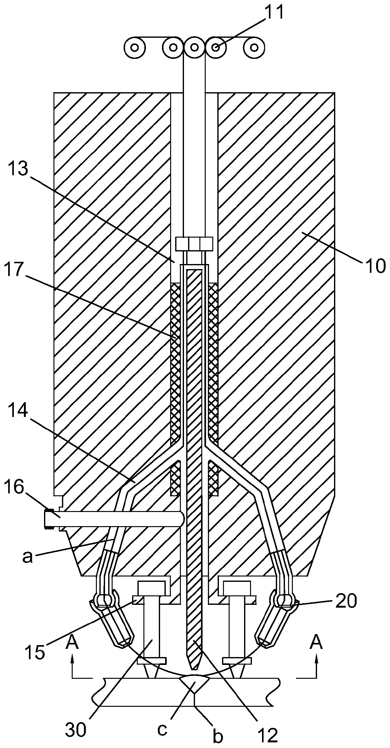
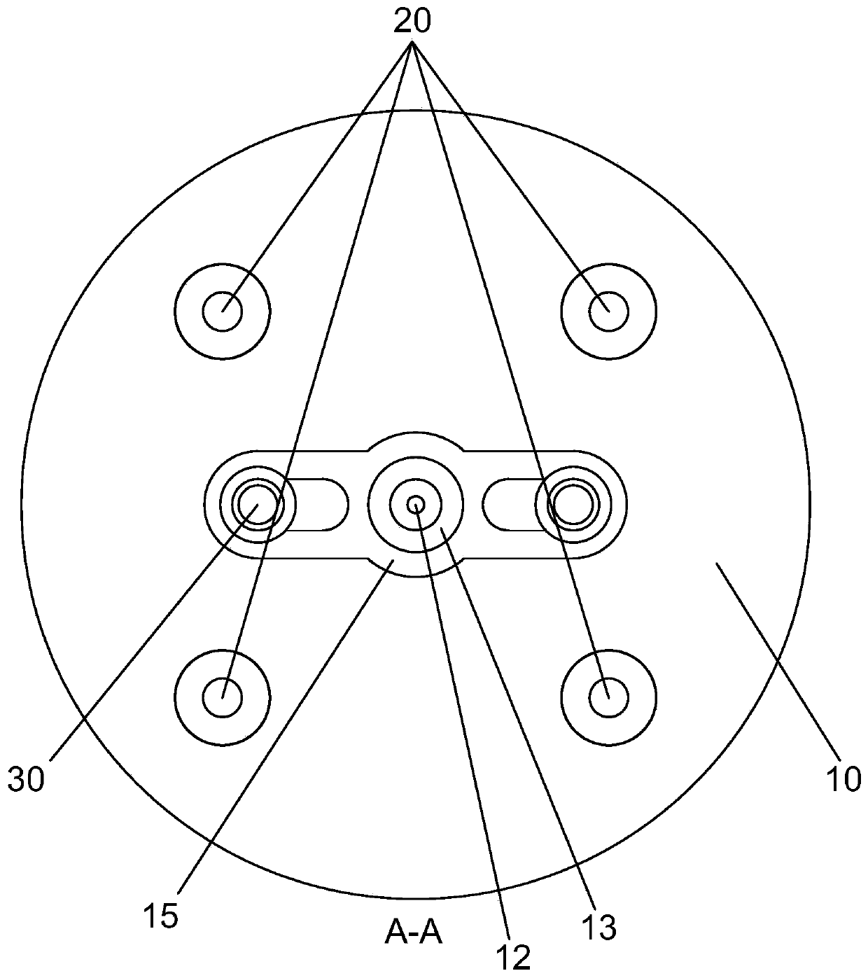
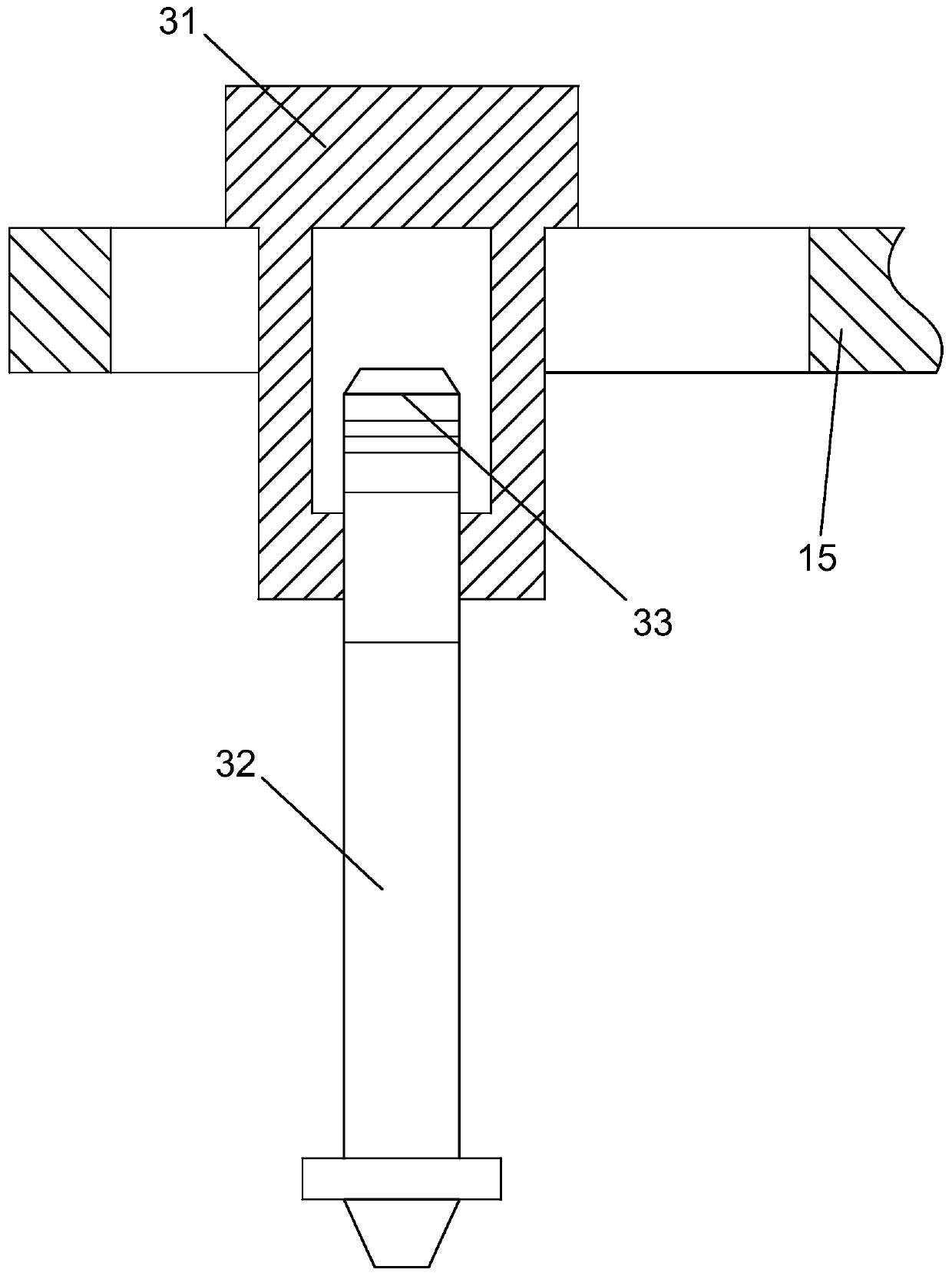
[0029] refer to Figure 1 to Figure 4 ,Such as Figure 1 to Figure 4 The shown ultrasonic argon arc welding device includes a welding torch 10 and a wire supply device 11, the welding torch 10 is provided with a metal electrode 12, the center of the welding torch 10 is provided with an electrode mounting hole 13, and the metal electrode 12 is inserted In the electrode installation hole 13, a wire feeder 20 is provided on the exposed end of the metal electrode 12 on the welding torch 10, and the wire feeder 20 is located at the periphery of the electrode installation hole 13. There is a wire feeding pipeline 14 connected to the electrode installation hole 13 and the wire ...


PUM


Abstract

The invention provides an ultrasonic argon arc welding device, which includes a welding torch, a metal electrode is arranged on the welding torch, an electrode installation hole is arranged in the center of the welding torch, and the metal electrode is inserted in the electrode installation hole. A wire feeding head is located at the exposed end of the metal electrode, and the wire feeding head is located at the periphery of the electrode installation hole, and a wire feeding pipe connecting the electrode installation hole and the wire feeding head is provided in the welding torch; The end of the welding gun with the wire feed head is also provided with an ultrasonic vibrating device. The ultrasonic vibrating devices are in two groups and arranged symmetrically on both sides of the metal electrode. The ends of the ultrasonic vibrating device and the two sides of the workpiece weld touch. The invention is suitable for different weld widths, and the welding wire supply is stable. The welding wire can be preheated by the metal electrode, and then the ultrasonic vibration device vibrates the weld seam, so that the metal structure at the weld seam is homogenized, the grain is refined, and the stress and strain are reduced. Air holes greatly improve the quality of welded joints.

Description

technical field [0001] The invention relates to the technical field of argon arc welding, in particular to an ultrasonic argon arc welding device. Background technique [0002] At present, argon arc welding is a common welding method in the welding field. The arc combustion of argon arc welding is stable, the heat is concentrated, the arc column temperature is high, the welding production efficiency is high, the heat-affected zone is narrow, the stress, deformation, and crack tendency of the welded parts are small, and the argon protection in argon arc welding can isolate the air The adverse effects of oxygen, nitrogen, hydrogen, etc. on the arc and molten pool can reduce the burning loss of alloy elements, so as to obtain dense, spatter-free, high-quality welded joints, and argon arc welding is open arc welding, operation and observation Convenience The electrode loss is small, the arc length is easy to maintain, and there is no flux or coating layer during welding, so it ...

Claims


Application Information

Patent Timeline
Patent Type & Authority Patents(China)
IPC IPC(8): B23K28/02
CPCB23K28/02
Inventor 陈希章苏传出
Owner WENZHOU UNIV
Why Eureka
Try Eureka