Base for steel plate cutting

A technology of steel plate and top plate, applied in the field of steel plate cutting base, can solve the problems such as difficulty in adjusting the height of the support rod, affecting the quality of steel plate cutting, low adjustment efficiency, etc. Reduce the effect of adjustment steps

Inactive Publication Date: 2017-06-13
YONGCHUAN DISTRICT CHONGQING HUAYI MACHINERY CASTING CO LTD
View PDF5 Cites 8 Cited by
  • Summary
  • Abstract
  • Description
  • Claims
  • Application Information

AI Technical Summary

Problems solved by technology

[0004] The above scheme solves the problems in the prior art by placing the steel plate on the height-adjustable support plate provided on the bottom plate for cutting, but the above scheme still has the following problems: 1. The support rod and the connecting rod of this scheme are threadedly connected , when the height of the bottom plate needs to be adjusted up, each support rod needs to be adjusted one by one, and the adjustment efficiency is very low; 2. After the adjustment of each support rod in this scheme, it is difficult to ensure the The adjustment height is uniform. If the height adjustment of each support rod is not uniform, it will cause the steel plate to be placed on the support rod and not be level, which will affect the quality of steel plate cutting

Method used


Image

  • Base for steel plate cutting

Examples


Embodiment 1

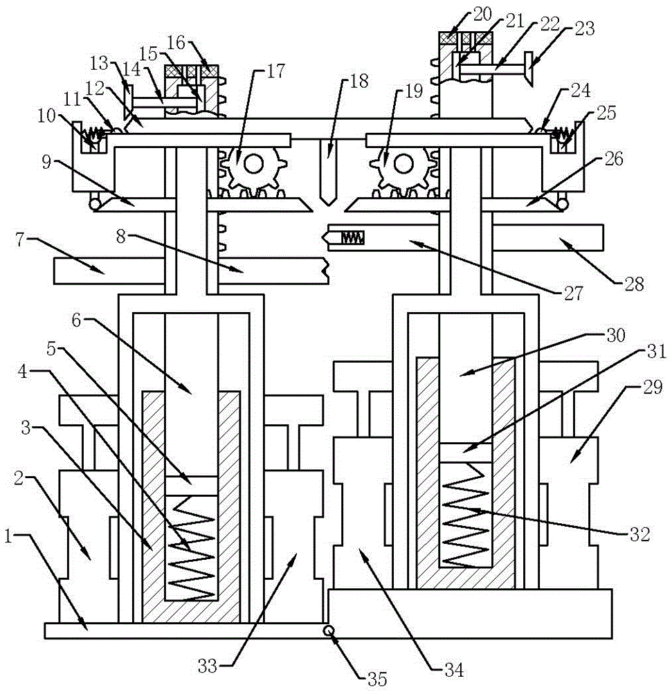
[0020] Embodiment one: if figure 1 As shown, the base for steel plate cutting includes a frame 1, on which a first sliding cylinder 3 and a second sliding cylinder located above the first sliding cylinder 3 are welded, and the first sliding cylinder 3 is slidably connected with a first top plate 5. The second top plate 31 is slidably connected in the second sliding cylinder, the first spring 4 is connected between the first top plate 5 and the first sliding cylinder 3, and the second spring is connected between the second top plate 31 and the second sliding cylinder 32. On the first top plate 5, there is a first pressing rod 6, which is slidably connected in the first sliding cylinder 3. On the second top plate 31, there is a second pressing rod 30, which is slidably connected. In the second sliding cylinder, there is a first cavity in the top of the first pressure rod 6, and the top of the first pressure rod 6 is provided with a first through hole communicating with the first...


PUM


Abstract

The invention discloses a base for steel plate cutting. The base comprises a frame; the frame is fixedly connected with two sliding cylinders; the sliding cylinders are provided with compression rods, namely a first compression rod and a second compression rod; negative pressure cavities are formed in the two compression rods, and are internally provided with pistons; the pistons are connected with a first wedge plate and a second wedge plate that are arranged at the exteriors of the negative pressure cavities; the first compression rod is engaged to a first gear; the first gear is engaged to a first rack; the first rack abuts against a first wedge rod; the first wedge rod abuts against a second wedge rod; the second compression rod is engaged to a second gear; the second gear is engaged to a second rack; the second rack abuts against a third wedge rod; the third wedge rod abuts against a fourth wedge rod; a fifth wedge rod which abuts against the first wedge plate and the second wedge plate is placed on the frame; the second wedge rod and the fourth wedge rod abut against the fifth wedge rod; the middle part of the fifth wedge rod is fixedly connected with a sixth wedge rod; and the first rack and the second rack abut against the sixth wedge rod. With the adoption of the base for the steel plate cutting, the adjustment efficiency and the cutting quality can be improved.

Description

technical field [0001] The present invention relates to the field of steel plate cutting devices, in particular to a base for steel plate cutting. Background technique [0002] In the processing of mechanical parts, steel plates are needed, and the finished steel plates are generally a larger piece, which needs to be cut into small pieces before they can be used to process parts, and the current cutting of steel plates Basically, it is carried out on the ground. The operator uses a cutting saw to cut the steel plate placed on the ground. After cutting off a small piece of steel plate, the cutting saw is easy to contact with the ground, and the ground will be easily damaged by the cutting saw. When cutting the steel plate, When the operator needs to cut one place, he needs to move the cutting saw to the next place that needs to be cut, which not only increases the labor intensity of the operator, but also is inconvenient to cut steel plates that are not in the same area. [...

Claims


Application Information

Patent Timeline
Patent Type & Authority Applications(China)
IPC IPC(8): B23Q3/08B23Q1/25
CPCB23Q1/25B23Q3/08
Inventor 孔锐
Owner YONGCHUAN DISTRICT CHONGQING HUAYI MACHINERY CASTING CO LTD
Why Eureka
Try Eureka