Automatic precision grinding device for outer surfaces of shaft type workpieces

A technology for shaft workpieces and outer surfaces, which is applied in the field of automatic fine grinding devices for the outer surfaces of shaft workpieces, and can solve problems such as the decline in the grinding accuracy of the outer surface of shaft workpieces, difficulty in further improving the grinding progress, and interference with the accuracy of the outer surface of shaft workpieces. , to achieve the effect of improving grinding efficiency, low cost, and good magnetic grinding effect

Inactive Publication Date: 2017-06-13
NANJING INST OF RAILWAY TECH
View PDF9 Cites 19 Cited by
  • Summary
  • Abstract
  • Description
  • Claims
  • Application Information

AI Technical Summary

Problems solved by technology

[0004] 1. When the grinding wheel grinding head is used to grind the outer surface of the shaft workpiece, the grinding wheel grinding head is in direct contact with the shaft workpiece, and the positioning accuracy of the grinding head and the shaft workpiece to be ground is required to be very high. The structure of the grinding machine is complex and requires professional operation, and the grinding cost High, when grinding shaft workpieces of different specifications, the operation and adjustment are more complicated and inefficient
[0005] 2. After the grinding wheel is worn, it will affect the grinding effect, and the grinding wheel is easy to be found and adjusted only when the degree of wear is relatively large, resulting in a decrease in the grinding accuracy of the outer surface of the shaft workpiece
[0006] 3. The grinding wheel grinding head of the grinding machine adopts a fixed grinding head to grind the outer surface of the shaft workpiece. The vibration generated by the grinding machine and the failure of the grinding head will interfere with the accuracy of the outer surface of the shaft workpiece, and the grinding progress is difficult to further improve.

Method used


Image

  • Automatic precision grinding device for outer surfaces of shaft type workpieces
  • Automatic precision grinding device for outer surfaces of shaft type workpieces
  • Automatic precision grinding device for outer surfaces of shaft type workpieces

Examples


Embodiment 1

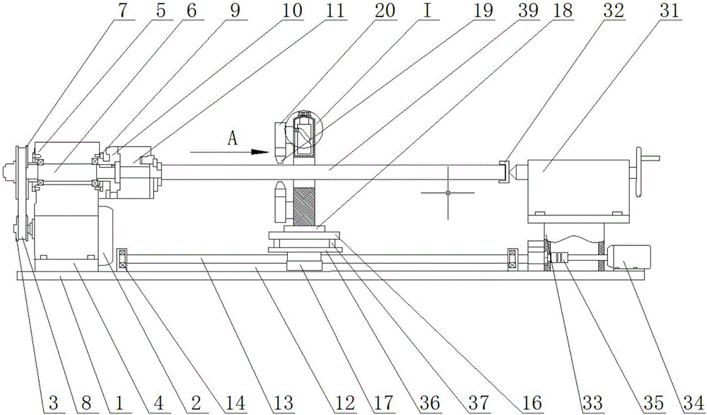
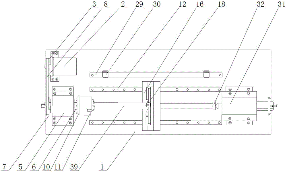
[0034] An automatic fine grinding device for the outer surface of a shaft workpiece, including a base plate 1, on which a first motor 2 is arranged. In this embodiment, the first motor is connected with the base plate by bolts, and the output shaft of the first motor 2 is A driving wheel 3 is provided, and a cushion block 4 is provided on one side of the first motor 2, and the cushion block 4 is fixedly connected with the bottom plate 1. In this embodiment, the bottom plate is connected with the cushion block by bolts. A transmission device is arranged on the pad 4, and the transmission device includes a first transmission box 5, and a transmission shaft 6 is arranged in the first transmission box 5, and the left and right ends of the transmission shaft 6 pass through the first transmission box 5. The casing wall is exposed outside the first transmission case 5, and a driven wheel 7 is arranged at one end of the transmission shaft 6, and a transmission belt 8 is installed betwe...


PUM


Abstract

The invention discloses an automatic precision grinding device for the outer surfaces of shaft type workpieces and relates to the technical field of magnetic grinding. The device comprises a baseplate, a heel block, a driving wheel, a driven wheel, a transmission belt, a main shaft end cover, a first transmission box, a positioning seat, a flange plate, a three-jaws self-centering chuck, a grinding device, a connecting block, a grinding support base, a workpiece positioning base, a tailstock, a second motor, a coupling, a screw positioning seat, a screw, a supporting plate, a nut, a sensor positioning seat, a limit sensor, a slide way, the nut and a sliding block. A punched hole is formed in the top and/or the side of the grinding support base, a cylindrical cam is arranged on a connecting rod, the cylindrical cam is provided with a rotating rod, the grinding support base is provided with an arc block, a rotary knob is installed on the arc block, and the rotating rod is sleeved with the rotary knob. The automatic precision grinding device for the outer surface of shaft type workpieces has the beneficial effects that the device is simple in operation, low in cost, capable of adapting to shaft type workpieces of different specifications , capable of improving the machining efficiency and capable of improving the precision and quality of the outer surface of the shaft workpieces.

Description

technical field [0001] The invention mainly relates to the technical field of magnetic grinding, in particular to an automatic fine grinding device for the outer surface of a shaft workpiece. Background technique [0002] In the industrial fields of machinery, electromechanical, and electric facilities, shaft workpieces, such as round shafts, screw screws, and straight pipes, are widely used in industrial equipment. With the increasing intelligence and integration of industrial equipment, higher requirements are placed on the stability and service life of the equipment. For shaft workpieces, the higher the accuracy of the outer surface, the higher the accuracy of the outer surface and other connecting parts. The more precise the coordination, the stronger the fatigue strength, reliability and corrosion resistance, which can improve the stable operation time of industrial equipment and provide the foundation and guarantee for the development of industrial equipment. [0003]...

Claims


Application Information

Patent Timeline
Patent Type & Authority Applications(China)
IPC IPC(8): B24B1/00B24B47/12B24B47/16B24B5/04B24B5/35
CPCB24B1/005B24B5/04B24B5/35B24B47/12B24B47/16
Inventor 朱颖莉
Owner NANJING INST OF RAILWAY TECH
Why Eureka
Try Eureka