Improved manipulator clamping jaw on component arranging equipment

A manipulator and equipment technology, applied in the field of manipulator jaws, can solve the problems of scratches left on the material, damage to the material, affecting the quality of the material, etc., to achieve the effect of simple structure and reduced damage

Pending Publication Date: 2017-06-13
DONGGUAN SHENGRONG AUTOMATION TECH CO LTD
View PDF5 Cites 9 Cited by
  • Summary
  • Abstract
  • Description
  • Claims
  • Application Information

AI Technical Summary

Problems solved by technology

However, the existing manipulators often use air cylinders for clamping. The clamped material is plugged and pulled out on the detection device. Plugging and unp

Method used


Image

  • Improved manipulator clamping jaw on component arranging equipment
  • Improved manipulator clamping jaw on component arranging equipment

Examples


Example Embodiment

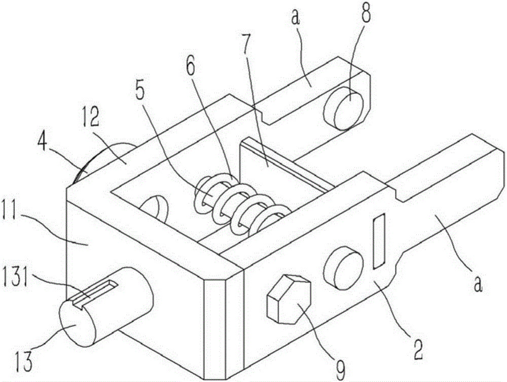
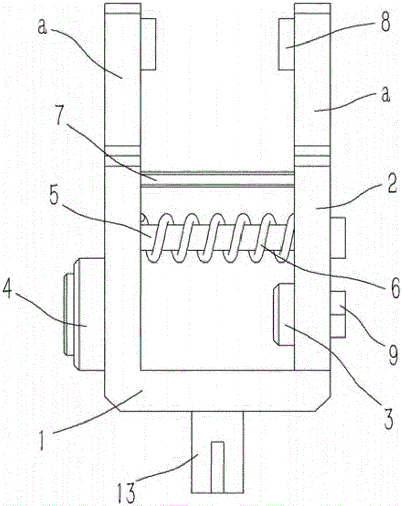
[0018] Example: see figure 1 , 2 As shown, an improved manipulator gripper on a part placement device includes an L-shaped positioning base 1 and a splint 2. The positioning base 1 is composed of a transverse portion 11 and a longitudinal portion 12, and the rear end of the splint 2 abuts against the positioning base 1. On the inner wall of the transverse portion 11, an iron block 3 is fixed on the inner side wall of the rear end of the splint 2, and an electromagnet 4 opposite to the iron block 3 is fixed on the longitudinal portion 12 of the positioning seat 1, and the splint 2 on the front side of the iron block 3 is inserted A T-shaped guide rod 5 is connected. The guide rod 5 is fixed on the longitudinal portion 12 of the positioning seat 1. A compression spring 6 is inserted and sleeved on the guide rod 5, and both ends of the compression spring 6 are pressed against the positioning seat 1 respectively. On the splint 2, a vertical baffle 7 is inserted into the splint 2 on ...


PUM


Abstract

The invention discloses an improved gripper of a manipulator on a piece placing device, comprising an L-shaped positioning seat and a clamping plate, the positioning seat is composed of a transverse part and a longitudinal part, and the rear end of the clamping plate abuts on the inner wall of the transverse part of the positioning seat, An iron block is fixed on the inner side wall of the rear end of the splint, an electromagnet opposite to the iron block is fixed on the longitudinal part of the positioning seat, and a T-shaped guide rod is inserted into the splint on the front side of the iron block, and the guide rod is fixed on the positioning seat. On the longitudinal part, a compression spring is inserted into the guide rod, and the two ends of the compression spring are respectively pressed against the positioning seat and the clamping plate. A vertical baffle is inserted into the clamping plate on the front side of the guiding rod, and the baffle is fixed. on the longitudinal portion of the positioning seat. The invention adopts magnetic clamping instead of the cylinder to clamp the material, and the clamping force can be changed by the current, so that the damage to the material can be reduced during clamping.

Description

[0001] Technical field: [0002] The invention relates to the technical field of component placement equipment, in particular to an improved manipulator gripper on the component placement equipment. [0003] Background technique: [0004] Component placement equipment, specifically, is an automated equipment that realizes fast insertion of parts on the PCB. It is controlled by a programmable controller and equipped with CCD, manipulator and man-machine interface. Then grab the material for plug-in detection to judge whether it is good or bad, and then scrap the test result or place the part to the corresponding position on the PCB. However, the existing manipulators often use air cylinders for clamping. The clamped material is plugged and pulled out on the detection device. Plugging and unplugging is easy to leave scratches on the material, affecting the quality of the material, and even when the force is large, it is easy to cause Material damage. [0005] Invention content:...

Claims


Application Information

Patent Timeline
IPC IPC(8): B25J15/06
CPCB25J15/0608
Inventor 李胜利
Owner DONGGUAN SHENGRONG AUTOMATION TECH CO LTD
Why Eureka
Try Eureka