
3D printer with high accuracy

A 3D printer, high-precision technology, applied in the direction of processing drive devices, additive processing, etc., can solve problems such as complex structure, deflection of nozzles, and large space occupied, so as to improve printing quality, ensure printing accuracy, and high feasibility Effect

Inactive Publication Date: 2017-06-13
JIAXING MINHUI AUTOMOTIVE PARTS CO LTD
View PDF5 Cites 6 Cited by
  • Summary
  • Abstract
  • Description
  • Claims
  • Application Information

AI Technical Summary

Problems solved by technology

The structure of this three-axis linkage transmission mechanism is relatively complex and takes up a large space. In addition, during the printing process, when moving between different positions, three drive units are required to drive the nozzle to move in sequence, so the printing efficiency is relatively low. Low
[0003] The patent application with the application number 201310246765.9 provides a kind of "more than three transmission assemblies distributed on the periphery of the platform, each transmission assembly includes a guide rod extending along the height direction, a sliding seat mounted on the guide rod, The driving motor used to drive the sliding seat to move up and down along the guide rod, and the connecting rod. The two ends of the connecting rod are respectively connected to the mounting seat and the sliding seat in a universally hinged manner. The seat adopts the traditional belt transmission method, which cannot guarantee an accurate transmission ratio, and it will be deflected when the nozzle is moving, which is very difficult to control

Method used


Image

  • 3D printer with high accuracy
  • 3D printer with high accuracy
  • 3D printer with high accuracy

Examples


Embodiment Construction

[0030] The present invention will now be described in further detail with reference to the drawings. These drawings are all simplified schematic diagrams, which merely illustrate the basic structure of the present invention in a schematic manner, so they only show the structures related to the present invention.

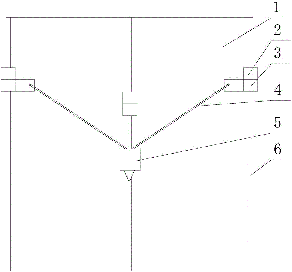
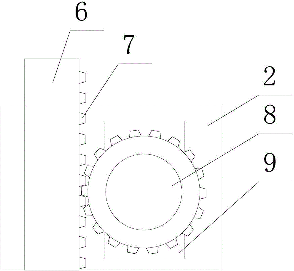
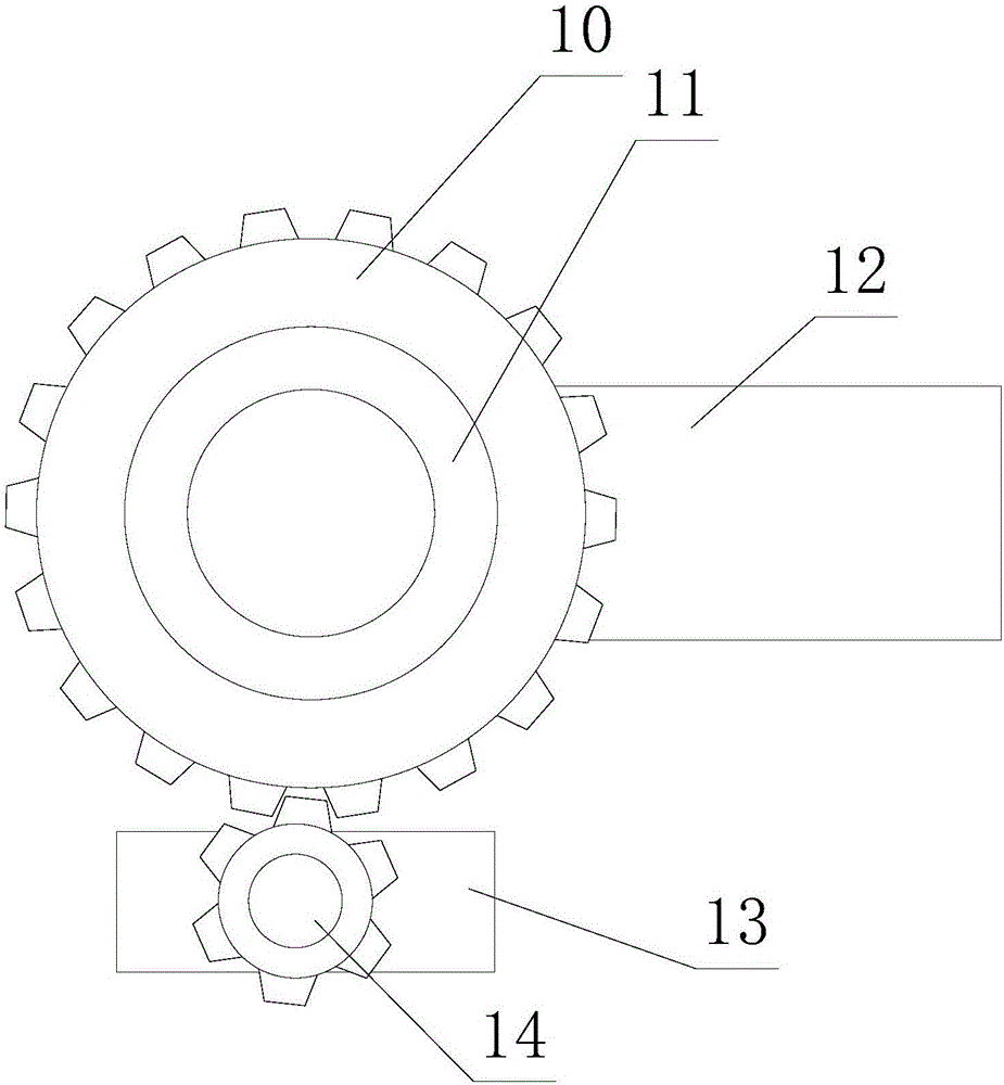
[0031] Such as Figure 1-6 As shown, a high-precision 3D printer includes a housing 1, a pillar 6, a slider 2, a rotating assembly 3, a connecting rod 4, a PLC, and a balance assembly 5;

[0032] The cross section of the housing 1 is triangular, the pillars 6 have three, the cross sections of the three pillars 6 are respectively displaced on the three corners of the section of the housing 1, the pillars 6 are arranged vertically, and the slider 2 has three , The three sliders 2 are respectively sleeved on the three pillars 6, the rotating assembly 3 has three, the three rotating assemblies 3 are fixedly arranged on the three sliders 2, the connecting rod 4 has three, the...


PUM


Abstract

The invention relates to a 3D printer with high accuracy. The 3D printer comprises a shell body, supporting columns, sliding blocks, rotating assemblies, connecting rods, a PLC and a balancing assembly. Each sliding block is further provided with a first motor and a first round gear. Each rotating assembly comprises a second round gear, a bearing, a supporting rod, a second motor and a third round gear. The balance assembly comprises third motors, a fixed block, lead screws, an adjusting block, a spraying head and a balance unit. The balance unit comprises a pulling rope, a sphere, limiting blocks, springs, a touch block and touch pieces. The 3D printer with the high accuracy is ingenious in design and high in feasibility, the height of the spraying head can be adjusted through sliding of the sliding blocks, the printing range of the spraying head can be enlarged through the rotating assemblies and the accuracy is high, and the spraying head can keep the vertical state all the time through the balance assembly, so that the printing accuracy is guaranteed, and the printing quality is improved.

Description

Technical field [0001] The invention relates to the field of printers, and in particular to a 3D printer with high accuracy. Background technique [0002] 3D printer is a kind of rapid prototyping technology. It is based on a digital model file, using powdered metal or plastic and other bondable materials to construct objects by printing layer by layer. The 3D printer is used to print the model, without the need for traditional cutting machine tools and molds. Under the control of the computer, the 3D entity can be directly formed according to the 3D model of the workpiece. The nozzle is the part used to output consumables in the 3D printer. The nozzle is required during the printing process. It can move arbitrarily in the space to deal with workpieces with different external contours. Most of the print head transmission mechanisms of the existing 3D printers use the transmission mechanism of the traditional three-axis linkage machine tool, that is, the axes along the X, Y, and ...

Claims


Application Information

Patent Timeline
Patent Type & Authority Applications(China)
IPC IPC(8): B29C64/227B33Y30/00
CPCB33Y30/00
Inventor 曹燕红
Owner JIAXING MINHUI AUTOMOTIVE PARTS CO LTD
Learn More