
Rod pumped well working condition diagnosis method integrated with electrical work diagram and indicator diagram

A technology for pumping wells and diagnostic methods, which is applied in construction and other fields, can solve the problems of dynamometer measurement, impact on benefits, single diagnostic method, etc., and achieve the effect of expanding the scope, improving the effect, and high accuracy

Inactive Publication Date: 2017-06-13
SINOPEC SHENGLI OILFIELD
View PDF0 Cites 10 Cited by
  • Summary
  • Abstract
  • Description
  • Claims
  • Application Information

AI Technical Summary

Problems solved by technology

[0002] In the production of pumping units in oilfields, although the dynamometer diagram diagnosis method is simple, reliable, intuitive, and rapid, it still has certain limitations: (1) According to the dynamometer diagram, only the downhole working conditions can be analyzed, and the ground pumping cannot be judged. The working conditions of the pumping unit, such as: the balance of the pumping unit, the failure of the gearbox, etc.; (2) For a small number of special oil wells, the indicator map cannot be measured, and other more convenient working condition diagnosis methods are needed; (3) The purchase and maintenance costs of the dynamometer measurement equipment are relatively high, which affects the efficiency
[0005] At present, in terms of working condition diagnosis of pumping wells, the dynamometer diagram and electric power diagram have initially realized the collection, monitoring and remote transmission of graphics. Providing continuous and accurate data sources and related calculation and diagnosis models cannot replace manual testing and diagnosis of oil well conditions, and realize real-time and intelligent analysis of oil well production conditions, and the diagnostic method is single, and its application has certain limitations

Method used


Image

  • Rod pumped well working condition diagnosis method integrated with electrical work diagram and indicator diagram

Examples


Embodiment Construction

[0028] The preferred embodiments of the present invention will be described below in conjunction with the accompanying drawings. It should be understood that the preferred embodiments described here are only used to illustrate and explain the present invention, and are not intended to limit the present invention.

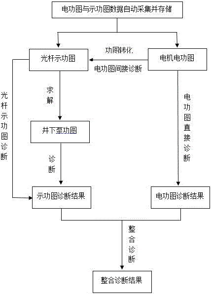
[0029] A method for diagnosing the working conditions of pumping wells integrated with the electric power diagram and the indicator diagram mentioned in the present invention comprises the following steps:

[0030] 1) Automatically collect and store the data of electric power diagram and indicator diagram in real time;

[0031] 2) In terms of working condition diagnosis of the indicator diagram, the diagnosis of the polished rod indicator diagram can be performed directly; if the polished rod indicator diagram fluctuates greatly, the downhole pump diagram can be diagnosed by using the one-dimensional wave equation with damping to solve the downhole pump diagram;

[...


PUM


Abstract

The invention relates to a rod pumped well working condition diagnosis method integrated with an electrical work diagram and an indicator diagram. The technical scheme includes steps of automatically collecting data of the electrical work diagram and the indicator diagram in real time and storing the data; for diagnosis of the working condition of the indicator diagram, directly diagnosing the indicator diagram of a polish rod; if the fluctuation of the indicator diagram of the polish rod is big, solving an underground pump work diagram by one-dimensional band damp fluctuation equation, and diagnosing the underground pump work diagram; for the diagnosis of the working condition of the electrical work diagram, using a mutual conversion model of the electrical work diagram and the indicator diagram, converting the electrical work diagram to the indicator diagram of the polish rod so as to perform the diagnosis of the indicator diagram, and realizing the indirect diagnosis of the electrical work diagram; setting up a diagnosis model of the electrical work diagram working condition, and realizing the direct working condition diagnosis of the electrical work diagram, wherein the working condition diagnosis result takes the diagnosis of the indicator diagram mainly and the diagnosis of the electrical work diagram secondarily. The invention has the beneficial effects of improving the working condition diagnosis precision, enlarging the diagnosis scale of the working condition, improving the real-time monitoring force of the oil well working condition, and enhancing the real-time and intelligent management of the oilfield.

Description

technical field [0001] The invention relates to a method for diagnosing the working condition of a pumping well, in particular to a method for diagnosing the working condition of a pumping well integrated with an electric power diagram and an indicator diagram. Background technique [0002] In the production of pumping units in oilfields, although the dynamometer diagram diagnosis method is simple, reliable, intuitive, and rapid, it still has certain limitations: (1) According to the dynamometer diagram, only the downhole working conditions can be analyzed, and the ground pumping cannot be judged. The working conditions of the pumping unit, such as: the balance of the pumping unit, the failure of the gearbox, etc.; (2) For a small number of special oil wells, the indicator map cannot be measured, and other more convenient working condition diagnosis methods are needed; (3) The purchase and maintenance costs of the dynamometer measuring equipment are relatively high, which af...

Claims


Application Information

Patent Timeline
IPC IPC(8): E21B47/008E21B47/009
CPCE21B47/008E21B47/009
Inventor 王增林陈军王欣辉陈德春谢文献高国强李永强常峰张瑞超王锦程徐加军
Owner SINOPEC SHENGLI OILFIELD
Learn More