Supersonic gas ejector

A technology of ejector and supersonic speed, which is applied in the direction of burner, gas fuel burner, combustion method, etc., can solve the problems that the long-term operation of wind tunnel equipment cannot be satisfied, the combustion parameters are difficult to adjust in real time, and cooling measures are difficult to adopt, and achieve Light weight, simple structure, and the effect of preventing air separation

Active Publication Date: 2017-06-13
CHINA ACAD OF AEROSPACE AERODYNAMICS
View PDF5 Cites 4 Cited by
  • Summary
  • Abstract
  • Description
  • Claims
  • Application Information

AI Technical Summary

Problems solved by technology

Make full use of heat energy to generate gas expansion, high efficiency, but the existing gas ejector is limited by the structural form, it is difficult to install a cooling device, and the time for reliable operation is very short
For example, the gas flow wind tunnel uses the gas ejector, which uses the injection combustion method of the rocket engine, uses the mixture of alcohol and oxygen for combustion, generates the total pressure, accelerates through the expansion of the nozzle, and generates the main air flow of the ejector. The injection efficiency is relatively high, but it is difficult to adopt cooling measures for the structure of the ejector shell parts. Generally, the heat capacity of the metal parts and the short running time are used to ensure safety. The running time is short, and the combustion parameters are difficult to adjust in real time. Convenience, but also unable to meet the long-term operation of wind tunnel equipment

Method used


Image

  • Supersonic gas ejector
  • Supersonic gas ejector
  • Supersonic gas ejector

Examples


Embodiment Construction

[0028] Below in conjunction with accompanying drawing, the present invention is described in further detail:

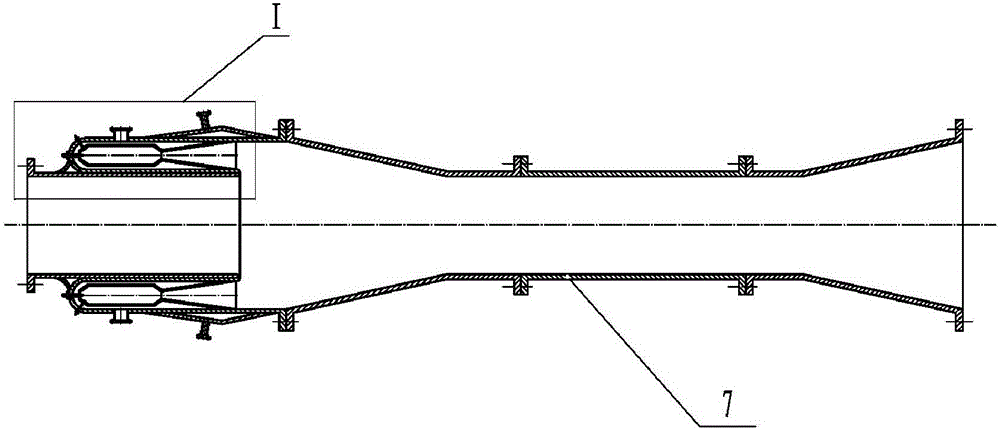
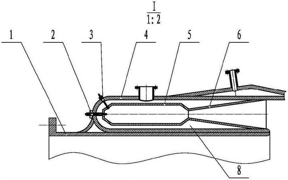
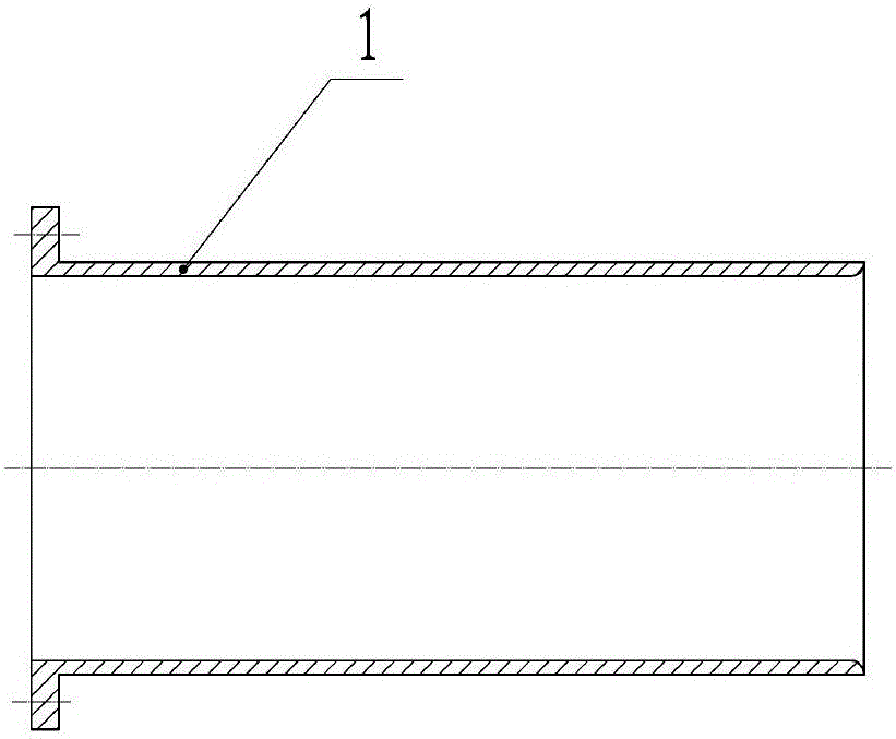
[0029] figure 1 It is a structural schematic diagram of the supersonic gas ejector of the present invention; Picture 1-1 yes figure 1 Zoom-in view of the middle I region. Such as figure 1 with Picture 1-1 As shown, the supersonic gas ejector includes: an air intake cylinder 1 , a fuel nozzle 2 , an igniter 3 , an ejector housing 4 , a combustion device and a diffuser device 7 . in,

[0030] The ejector housing 4 is sheathed on the outer surface of the intake tube 1 , and a cavity 8 is formed between the ejector housing 4 and the intake tube 1 . Specifically, the ejector housing 4 is sleeved on the outer surface of the air intake cylinder 1, an annular cavity 8 is formed between the ejector housing 4 and the air intake cylinder 1, and the axis of the ejector housing 4 is aligned with the air intake cylinder. The axes of 1 are the same axis.

[0031] The combu...


PUM


Abstract

The invention discloses a supersonic gas ejector. The supersonic gas ejector comprise a gas inlet barrel, a fuel nozzle, an igniter, an ejector housing, a combustion device and a diffusion device, wherein the ejector housing sleeves the outer surface of the air inlet barrel, and a cavity is formed between the ejector housing and the air inlet barrel; the combustion device is arranged in the cavity; the combustion device comprises a combustion barrel and a spray tube; the igniter is connected to the combustion barrel through the ejector housing; the spray tube is connected to the back end of the combustion barrel; and the diffusion device is connected to one end of the ejector housing. The device disclosed by the invention employing high-temperature gas expansion is high in thermal efficiency, suitable for long-term operation, simple in structure, easy to process and low in manufacturing cost.

Description

technical field [0001] The invention relates to the field of fluid machinery, in particular to a supersonic gas ejector. Background technique [0002] An ejector is a fluid machine that creates a low pressure environment through the expansion of a gas to suck another fluid. Conventional hypersonic wind tunnels use air ejectors to generate a low-pressure environment in the test chamber, and discharge the low-pressure test gas into the atmosphere. According to the different ejection gas media, commonly used ejectors include air ejectors, steam ejectors, etc. device, gas injector. [0003] The air ejector uses compressed air to accelerate through the nozzle to generate gas expansion. Because it is a cold flow, when the Ma number is high, the air flow will condense, and the efficiency is relatively low. [0004] The steam ejector requires a steam boiler and a long heat pipe system, the equipment is huge, and the flow rate of the ejection system is large. It is necessary to bui...

Claims


Application Information

Patent Timeline
IPC IPC(8): F23D14/04F23D14/64
CPCF23D14/04F23D14/64
Inventor 郭孝国江泽鹏
Owner CHINA ACAD OF AEROSPACE AERODYNAMICS
Why Eureka
Try Eureka