
Pipe flow velocity sensor and application method thereof

A technology of flow velocity sensor and pressure sensor, which is applied in fluid velocity measurement, instrumentation, velocity/acceleration/shock measurement, etc. It can solve the problems of large flow resistance of impeller type flowmeter, high requirements for using ring, difficult installation, etc., and achieve stability Good, uniform force transmission, easy to replace the effect

Inactive Publication Date: 2017-06-13
WUXI LEHUA AUTOMATION TECH
View PDF7 Cites 2 Cited by
  • Summary
  • Abstract
  • Description
  • Claims
  • Application Information

AI Technical Summary

Problems solved by technology

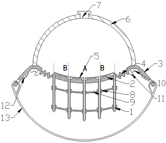
[0007] The technical problem to be solved by the present invention is: to overcome the technical problems in the prior art, such as the high cost of optical and acoustic flow meters, the high requirements for the use of rings, the large flow resistance of the impeller type flow meter, and the difficulty in installation, etc., to provide a pipeline flow velocity sensor and use method

Method used


Image

  • Pipe flow velocity sensor and application method thereof

Examples


Embodiment Construction

[0044] The present invention is described in further detail now in conjunction with accompanying drawing. These drawings are all simplified schematic diagrams, which only illustrate the basic structure of the present invention in a schematic manner, so they only show the configurations related to the present invention.

[0045] Such as figure 1 , a pipeline flow velocity sensor, including a base plate, the base plate includes a support plate and fixed surfaces located on both sides of the support plate, a vibration damping area is arranged between the support plate and the fixing surface, and the thickness of the vibration damping area is less than The thickness of the support plate and the fixed surface, the damping area is a continuous zigzag buffer structure, wherein a spoiler array is fixed on the support plate, and the fixed substrate of the spoiler array is connected to the support plate by screws ;

[0046] The spoiler array includes a fixed substrate and several spo...


PUM


Abstract

The invention relates to a pipe flow velocity sensor and an application method thereof. The pipe flow velocity sensor comprises a substrate, the substrate comprises a support plate and fixing surfaces on both sides of the support plate, and the support plate is fixedly provided with a spoiler array; the spoiler array comprises a fixing substrate and a plurality of spoilers vertically fixed onto the fixing substrate; the fixing substrate of the spoiler array is adhered to the support plate; the fixing substrate is provided with a plurality of pressure sensors; the upper portion of the support plate is provided with a closing case, the edge of the closing case and the support plate are connected in a closed mode; an expansion cavity is formed between the closing case and the support plate and filled with high-pressure inert gas. The pipe flow velocity sensor also comprises a data processing circuit; the data processing circuit comprises converters connected with the pressure sensors for converting data of the pressure sensors into electrical signals, and data processors connected with the converters of the pressure sensors for computing and converting the electrical signals output by the converters.

Description

technical field [0001] The invention relates to a pipeline flow velocity sensor and a usage method, belonging to the field of pipeline flow velocity sensors. Background technique [0002] As a device for measuring the velocity of water flow, the flow meter can be divided into several categories according to the field, such as mechanical type, optical type, and acoustic wave type, among which: [0003] The optical type and the acoustic wave type have high data acquisition accuracy, timely flow rate feedback, and no attenuation on the pipeline flow rate. They are widely used in some high-precision fields, such as: pharmaceuticals, precision chemicals, fluid model building, pipelines and pumps, etc. Precision fluid conveying equipment testing, etc.; optical type and acoustic type are mainly manufactured through media such as sound waves and electromagnetic waves, using the concept of different attenuation effects and different propagation speeds on sound waves and electromagnet...

Claims


Application Information

Patent Timeline
Patent Type & Authority Applications(China)
IPC IPC(8): G01P5/02
CPCG01P5/02
Inventor 钱国东
Owner WUXI LEHUA AUTOMATION TECH
Learn More