Plate heat exchanger unit and connecting structure

A plate heat exchanger and plate technology, applied in the direction of heat exchanger types, indirect heat exchangers, laminated elements, etc., can solve the problems that hinder the industrial application process of high temperature heat pipe heat exchangers, and the unreasonable and abnormal connection of transition sections. Work status and other issues, to achieve the effect of rich connection forms, low production equipment requirements, and convenient installation

Inactive Publication Date: 2017-06-16
苏州三川换热器股份有限公司
View PDF11 Cites 0 Cited by
  • Summary
  • Abstract
  • Description
  • Claims
  • Application Information

AI Technical Summary

Problems solved by technology

[0004] High-temperature shell-and-tube heat exchangers are commonly used in flue gas coolers, which are mainly used for heat exchange between liquid media and flue gas. They have the following disadvantages: 1. Huge structure and high cost, which greatly hinder the industrial applicat

Method used


Image

  • Plate heat exchanger unit and connecting structure
  • Plate heat exchanger unit and connecting structure
  • Plate heat exchanger unit and connecting structure

Examples


Embodiment

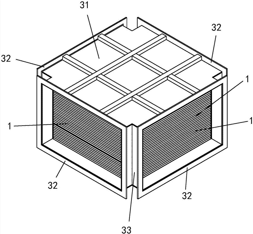
[0066] See attached Figure 1~Figure 17 As shown, a plate heat exchanger unit includes a core body and an outer frame, and the core body is accommodated in the outer frame, wherein:

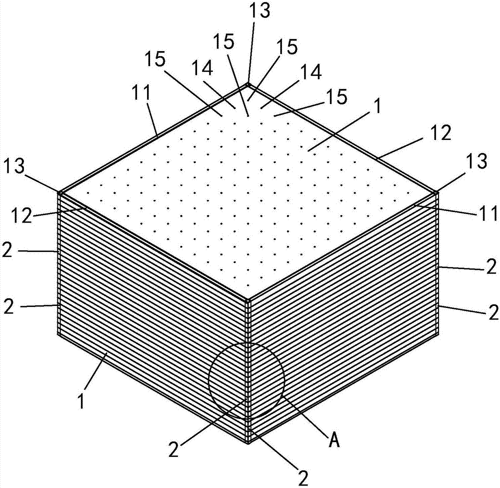
[0067] It includes several plates 1, and each plate 1 is stacked in its thickness direction.

[0068] The main body of the plate 1 is a square metal plate, the two surfaces of the square metal plate are respectively defined as the front and the back, and the four sides of the square metal plate are defined as the first side, the second side in the clockwise direction or the counterclockwise direction. Second side, third side and fourth side.

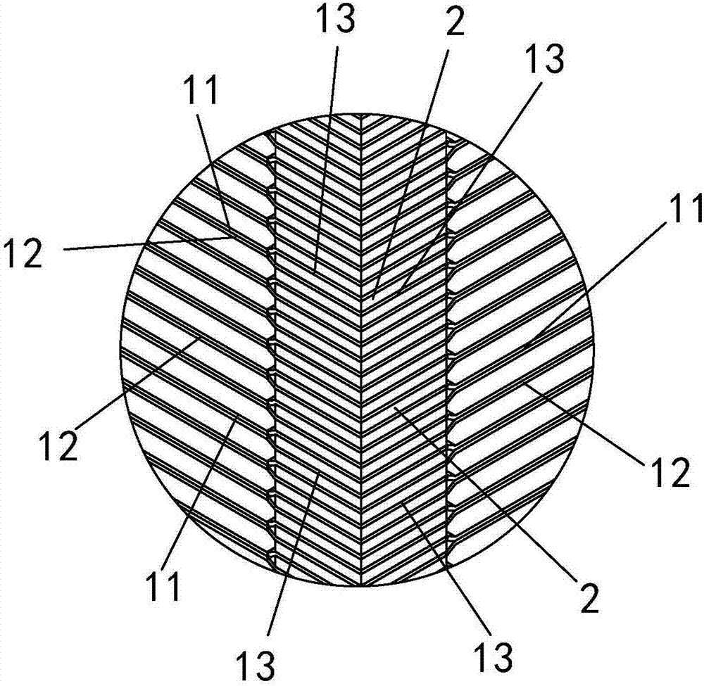
[0069] The edges of the first side and the third side are provided with a first folding bar 11 towards the front side of the square metal plate; There is a second folding bar 12.

[0070] There is a transition plate 13 at the junction of each adjacent first folded strip 11 and second folded strip 12, and the transition plate 13 is located on the same pla...


PUM


Abstract

The invention relates to a plate heat exchanger unit and a connecting structure. The plate heat exchanger unit is characterized by comprising a core body and an outer frame. The core body is accommodated in the outer frame. The core body comprises a plurality of plate pieces, and the plate pieces are overlapped in the thickness direction thereof. Concave points and convex points are arranged at the center of a square metal plate in an array mode. The convex points on each plate piece are in contact with the corresponding convex points on the adjacent plate pieces, corner seal blocks are arranged between transition plates of the adjacent plate pieces, the corner seal blocks are blocky components and fill spaces between the transition plates of the adjacent plate pieces, and the corner seal blocks are fixedly connected with the transition plates. The outer frame comprises at least two side plates and a plurality of frames. The two side plates are arranged on the two sides of the core body respectively, the frames are arranged on the peripheries of the side plates, and the frames are arranged in the circumferential direction of the side plates at intervals. The core body is fixedly connected with the outer frame. Every two adjacent plate heat exchanger units are fixedly connected through a clamp.

Description

technical field [0001] The invention relates to a heat exchanger, in particular to a plate heat exchanger unit and a connection structure. Background technique [0002] Now that the smog covers the sky and the sun, it is rampant across China. The people's desire to reduce the smog is extremely strong. The smog has also become one of the obstacles to China's environmental improvement. To control it, we must first treat it from the source. [0003] Heating boilers, thermal power plants, etc. burn a lot of coal, and the high-temperature gas produced contains a lot of smoke and harmful gases, which are discharged into the atmosphere and take away a lot of valuable heat. Many large boiler coal-fired plants also have related Exhaust gas treatment measures, but the equipment is huge, covers a large area, the whole system equipment is expensive, and the cost recovery is far away, and it is even unaffordable for small coal-fired boiler plants. We know that the best opponent to deal ...

Claims


Application Information

Patent Timeline
IPC IPC(8): F28D9/04F28F3/08
CPCF28D9/0037F28D9/04F28F3/08
Inventor 李建明
Owner 苏州三川换热器股份有限公司
Why Eureka
Try Eureka