

Monitoring system for irrigation
A monitoring system and processor technology, applied in the field of the Internet of Things, can solve the problems of high network energy consumption, low data monitoring accuracy, and inability to guarantee crop production and output, and achieve the effect of saving energy and reducing costs.
- Summary
- Abstract
- Description
- Claims
- Application Information
AI Technical Summary
Problems solved by technology
Method used
Image

Examples
Embodiment 1
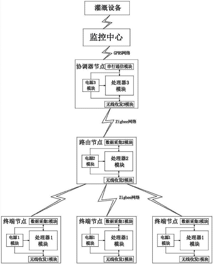
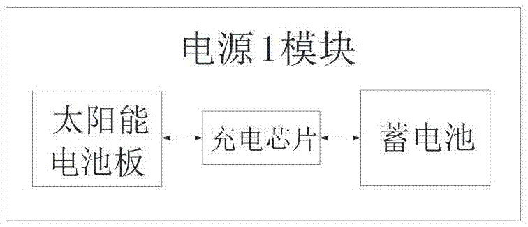
[0018] like figure 1 and figure 2 As shown, a monitoring system for irrigation includes multiple terminal nodes, routing nodes, coordinator nodes, irrigation equipment, and a monitoring center for controlling irrigation equipment. Module connected data acquisition 1 module, wireless transceiver 1 module and power supply 1 module, routing node includes processor 2 module, data acquisition 2 module connected to processor 2 module, wireless transceiver 2 module and power supply 2 module, coordinator node Including processor 3 module, wireless transceiver 3 module, serial communication module and power supply 3 module all connected to processor 3 module, wireless transceiver 1 module transmits the data collected by data acquisition 1 module to wireless transceiver 2 module and wireless transceiver 2 module through Zigbee network The wireless transceiver 3 module, the wireless transceiver 2 module transmits the data collected by the data acquisition 2 module to the wireless trans...
PUM
 Abstract
Description
Claims
Application Information