Material pulverizer with dust removal function

A pulverizer and pulverizer motor technology, which is applied in the field of material pulverizers and dust-removable material pulverizers, can solve the problems of pulverizers without dust removal, poor ventilation, and production difficulties, so as to improve production efficiency and product quality. Easy to adjust and maintain, easy to carry and install

Inactive Publication Date: 2017-06-20
CHONGQING SHANGSHANG SCI & TECH CO LTD
View PDF0 Cites 6 Cited by
  • Summary
  • Abstract
  • Description
  • Claims
  • Application Information

AI Technical Summary

Problems solved by technology

Since the gap between the crushing hammer of the pulverizer and the shell is large, and the separation screen is set at the semicircle at the lower part of the shell, the area for the crushed material to pass through the separation screen is small, which will affect the production volume, so the production efficiency is low
Since the induced draft fan and the pulverizer operate coaxially, the speed of the pulverizer and the induced air volume of the induced fan cannot be adjusted separately at any time, which brings certain difficulties to production.
Due to the large bending degree of the separated finished powder entering the dust removal process in the powder collector, and the strong adhesion of the crushed material, it is easy to stick to the bending place, making it difficult to ensure normal production.
Since the bag is used for powder collection and dust removal, if it is used for a long time, the fine powder will adhere to a large area in the bag, making it difficult to exhaust, which will not only affect the product quality, but also lead to high negative pressure and load on the motor. Increase or even damage the motor, which will bring trouble to production, and the existing pulverizer does not have the function of dust removal, which will pollute the regional environment and cause the regional dust to exceed the standard

Method used


Image

  • Material pulverizer with dust removal function

Examples


Embodiment

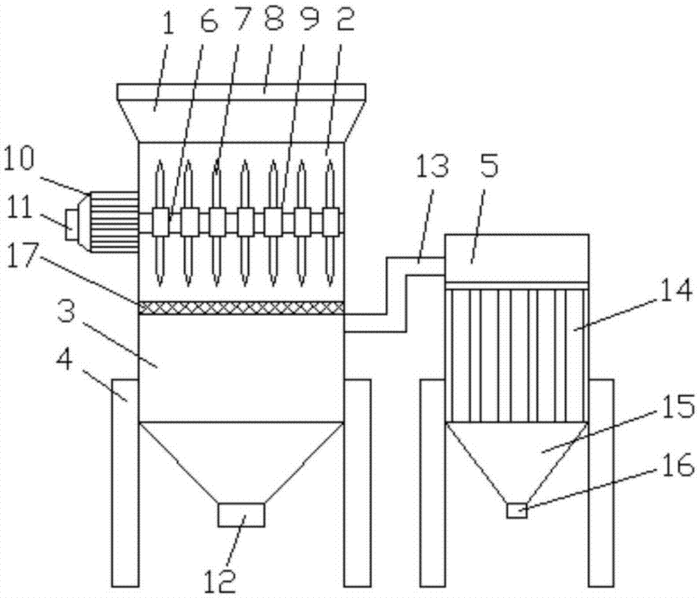
[0017] Example: see figure 1 , a kind of dedusting material pulverizer of the present invention comprises pulverization chamber 2, separation chamber 3, dedusting chamber 5, pulverization rotating shaft 6, feeding cover 8, pulverization motor 10, dust removal bag 14 and vibrating screen 17, and described pulverization chamber 2 A feed hopper 1 is arranged on the upper side, and a crushing shaft 6 is arranged inside the crushing chamber 2, and the crushing shaft 6 axially penetrates the crushing chamber 2, and a crushing motor 10 is fixedly installed at one end of the crushing shaft 6, and the crushing motor 10 10 is arranged on the outer wall of the crushing chamber 2, the lower side of the crushing chamber 2 is provided with a separation chamber 3, the lower side of the separation chamber 3 is provided with a separation outlet 12, and the upper side of the separation chamber 3 is provided with a dust discharge pipe 13, so The other end of the dust discharge pipe 13 is connect...


PUM


Abstract

The invention belongs to the technical field of crushing machinery and discloses a dust-removable material grinder, which includes a crushing chamber, a separation chamber, a dust removal chamber, a crushing shaft, a feeding cover, a crushing motor, a dust removal bag and a vibrating screen. The upper side of the crushing chamber is A feed hopper is provided, and a crushing shaft is arranged inside the crushing chamber, and the crushing shaft axially penetrates the crushing chamber, and a crushing motor is fixedly installed at one end of the crushing shaft, and the crushing motor is arranged on the wall of the crushing chamber. The lower side of the chamber is provided with a separation chamber, the lower side of the separation chamber is provided with a separation outlet, the upper side of the separation chamber is provided with a dust discharge pipe, and the other end of the dust discharge pipe is connected with a dust removal chamber. The lower side of the chamber is fixedly provided with support frames. The invention has good pulverization and dust removal effects, high powder forming rate, can effectively improve production efficiency and product quality, not only can make the product quality meet the ministerial standard, but also can make the dust emission reach the qualified standard required by the state for environmental protection.

Description

technical field [0001] The invention relates to a material pulverizer, in particular to a dust-removable material pulverizer, which belongs to the technical field of pulverizing machinery and equipment. Background technique [0002] At present, the pulverizers in my country are mainly composed of a pulverizer and an induced draft fan connected to it and a bag-type powder collector. The pulverizer is composed of a casing and a pulverizing hammer and a separating screen. Since the gap between the pulverizing hammer of the pulverizer and the shell is large, and the separating screen is set at the lower semicircle of the shell, the area where the pulverized material passes through the separating screen is small, which will affect the production volume, so the production efficiency is low. Since the induced draft fan and the pulverizer operate coaxially, the rotating speed of the pulverizer and the induced air volume of the induced draft fan cannot be adjusted separately at any ...

Claims


Application Information

Patent Timeline
Patent Type & Authority Applications(China)
IPC IPC(8): B02C18/14B02C18/16B02C23/14B02C18/22B08B15/04
CPCB02C18/14B02C18/16B02C18/2225B02C23/14B08B15/04
Inventor 黄燕
Owner CHONGQING SHANGSHANG SCI & TECH CO LTD
Why Eureka
Try Eureka