
Casting demolding cleaning and spraying device

A spraying device and casting demoulding technology, which is applied to casting equipment, manufacturing tools, and equipment for transporting molds, etc., can solve the problems of increased casting cost, unevenness, waste of mold release liquid, etc., and achieve reduced production costs and thin film layers. Uniform and reduce the effect of defective rate

Active Publication Date: 2017-06-20
安徽凯斯汀科技有限公司
View PDF9 Cites 1 Cited by
  • Summary
  • Abstract
  • Description
  • Claims
  • Application Information

AI Technical Summary

Problems solved by technology

After the newly cast components are taken out of the mold, there is often residual waste liquid left in the mold, so it is necessary to clean the inside of the mold, and in order to facilitate the casting components in the mold to be released from the mold, it is often The release agent is sprayed in the mold cavity, so the traditional casting equipment will directly spray the release liquid on the cavity position on the mold after taking out the casting components in the mold, spray the mold cavity for casting clean, and at the same time the release liquid A release layer is formed in the mold cavity, so that the liquid raw material in the casting mold cavity can be easily separated after solidification and molding
This casting production method will cause a lot of waste of release liquid, increasing the cost of casting
Moreover, it is difficult to thoroughly clean the molding cavity of the mold, and the mold release liquid sprayed by traditional casting equipment is not uniform enough in the molding cavity of the mold, which makes the castings formed during the casting process prone to defects

Method used


Image

  • Casting demolding cleaning and spraying device
  • Casting demolding cleaning and spraying device
  • Casting demolding cleaning and spraying device

Examples


Embodiment Construction

[0013] Below in conjunction with embodiment the present invention is further described:

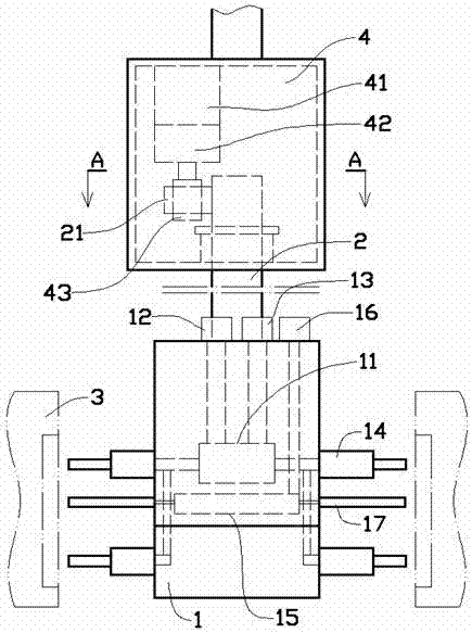
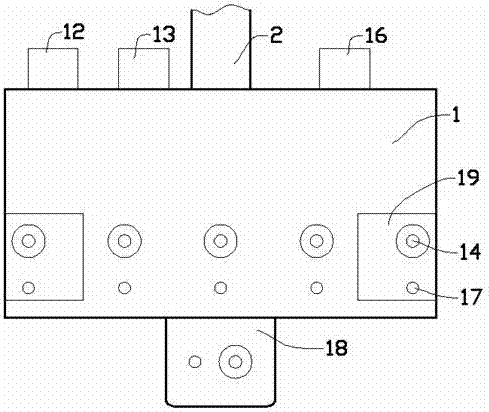
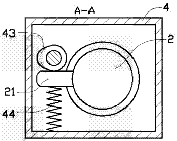
[0014] Such as figure 1 and figure 2 As shown in the embodiment, the casting demoulding cleaning and spraying device includes an installation block 1, and the installation block 1 is assembled on the mechanical arm through the connecting column 2, and the mechanical arm is fixedly assembled on the frame of the casting machine. The casting mold 3 of the above-mentioned casting machine includes two pieces that can be opened and closed horizontally on the left and right. The installation block 1 can be driven by the mechanical arm to the middle of the two separate casting molds of the casting machine; the inside of the installation block 1 is designed with a liquid buffer Cavity 11, the upper part of the installation block 1 is respectively designed with a clean water interface 12 and a release liquid interface 13 connected with the liquid buffer chamber 11; the clean water interface 12 is...


PUM


Abstract

The invention provides a casting demolding cleaning and spraying device. The casting demolding cleaning and spraying device comprises an installing block. A liquid buffering cavity is designed in the installing block. A clean water connector and a demoulding liquid connector which communicate with the liquid buffering cavity are designed at the upper portion of the installing block. Liquid spraying pipes horizontally stretching out are assembled on the front face and the back face of the installing block and communicate with the liquid buffering cavity. A gas buffering cavity is designed in the lower portion of the liquid buffering cavity. An airflow connector communicating with the gas buffering cavity is further designed in the upper portion of the installing block. An air spraying pipe horizontally stretching out is further assembled on the front face and the back face of the installing block. The liquid spraying pipes and the air spraying pipe are right opposite to the inner wall of a forming cavity in a casting die. When the device works, the casting die can be rapidly cooled, a uniform film can be formed in the forming cavity through the demoling liquid, and the casting defective rate is greatly reduced. Meanwhile, the usage amount of the demolding liquid is reduced, and the production cost is reduced.

Description

technical field [0001] The invention relates to the technical field of casting equipment, in particular to a casting demoulding cleaning and spraying device. Background technique [0002] Casting is a method in which liquid metal is poured into a casting cavity adapted to the shape of the part, and after it is cooled and solidified, the part or blank is obtained. In the casting production process, the metal raw material needs to be heated and melted first, and then the metal solution is poured into the casting cavity formed by two casting molds. After the molten metal is formed in the casting cavity, the casting mold is separated, and the cast mold is taken out. After the newly cast components are taken out of the mold, there is often residual waste liquid left in the mold, so it is necessary to clean the inside of the mold, and at the same time, in order to facilitate the casting components in the mold to be released from the mold, it is often The release agent is sprayed...

Claims


Application Information

Patent Timeline
IPC IPC(8): B22D33/04B22D45/00
CPCB22D33/04B22D45/00
Inventor 汪加虎
Owner 安徽凯斯汀科技有限公司
Learn More