Method for the surface compaction and calibration of a sintered component

A technology of densification and mould, applied in the direction of forming tools, manufacturing tools, material forming presses, etc., can solve the problems of limited use, unfavorable mechanical properties, etc., and achieve the effect of improving the precision of components

Active Publication Date: 2017-06-20
MIBA SINTER AUSTRIA
View PDF6 Cites 1 Cited by
  • Summary
  • Abstract
  • Description
  • Claims
  • Application Information

AI Technical Summary

Problems solved by technology

However, the greater or lesser degree of porosity of the sintered component due to the manufacturing method has a negative effect on the mechanical properties of the sintered component, thereby limiting the use of components produced by powder metallurgy

Method used


Image

  • Method for the surface compaction and calibration of a sintered component
  • Method for the surface compaction and calibration of a sintered component
  • Method for the surface compaction and calibration of a sintered component

Examples


Embodiment Construction

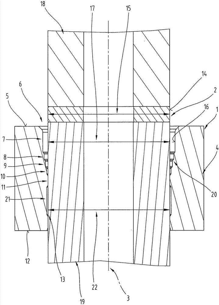
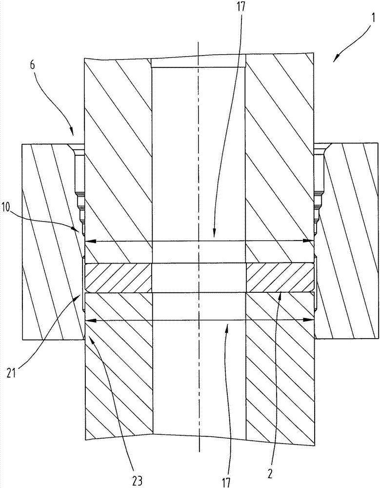
[0023] First of all, it should be confirmed that in the differently described embodiments, the same parts have the same reference signs or the same component designations, wherein the disclosure content contained in the entire description can be transferred to the same figure with the same figure Mark or on the same part of the same component name. Furthermore, selected positional descriptions in the description, such as top, bottom, side, etc., refer to the currently described or illustrated drawing and can be transferred to a new position in the event of a change of position.

[0024] It should be noted here that the calibration of the sintered component means that the sintered component is processed in a mold by a compression load in order to achieve at least approximately the theoretical dimensions of the component. "At least approximately" here means that deviations from the theoretical dimensions within customary tolerances are permissible.

[0025] The term "theoretica...


PUM


Abstract

The invention relates to a method for the surface compaction and calibration of a sintered component (2). According to the method, the sintered component (2) runs along an axis (3) through a plurality of die sections (7-11) of a die (1), the inner diameter (17) of which decreases in pressing direction and wherein the individual die sections (7-11) are arranged such that a following die section (8-11) of the plurality of die sections (7-11) directly adjoins the corresponding die section (7-10) which precedes it in pressing direction, and after the surface compaction at the last die section (11) with decreasing inner diameter (17) there is a relaxation of the sintered component (2) in a relief section (21) directly adjoining the last die section (11), which relief section has a greater diameter (22) than the immediately preceding last die section (11) of the die section (7-11) with a decreasing inner diameter (17). The sintered component (2) is calibrated in the relief section, whereby the inner contour of the relief section (21) corresponds with the intended contour with the nominal dimensions of the sintered component (2).

Description

technical field [0001] The invention relates to a method for surface densification and alignment of a sintered component, according to which the sintered component is moved along an axis from a first mold opening of a mold towards a mold opening opposite the first mold opening along said axis The second mold opening is moved, wherein the sintered component passes through several mold segments of the mold during said movement, and the surface area of ​​the sintered component is now densified, for which reason the inner diameters of successive mold segments along the The extrusion direction becomes smaller, and the individual mold sections are arranged such that the latter mold section of the plurality of mold sections is directly connected to the corresponding preceding mold section in the extrusion direction, and so that in the case of After the surface densification in the last mold section of reduced inner diameter, the relaxation of the sintered part takes place in a relief...

Claims


Application Information

Patent Timeline
Patent Type & Authority Applications(China)
IPC IPC(8): B22F3/03B22F3/16B22F3/24
CPCB21D37/08B22F3/03B22F3/16B22F3/24B30B9/28B30B11/025B30B15/028B22F3/1017B22F3/164B22F2003/166
Inventor H·勒斯勒尔H·施密德M·施泰因毛雷尔K·迪金格尔
Owner MIBA SINTER AUSTRIA
Why Eureka
Try Eureka