
Roller type metallurgy powder mixing device

A metallurgical powder and material mixing device technology, which is applied in transmission devices, gear transmission devices, belts/chains/gears, etc., can solve the problems of restricting the production efficiency of mixing materials, and achieve the effect of balanced ratio of each diameter and sufficient mixing

Active Publication Date: 2017-06-20
深圳市泛海统联精密制造股份有限公司
View PDF6 Cites 9 Cited by
  • Summary
  • Abstract
  • Description
  • Claims
  • Application Information

AI Technical Summary

Problems solved by technology

The existing powder metallurgy production process generally prepares powder particles of suitable particle size first, then presses them into shape, and then sinters them to form parts with fixed shapes. The density and product performance after sintering are directly related to the size of powder particles. The requirements of the products are different, and powder particles of different particle sizes need to be uniformly mixed in different proportions to achieve the desired effect. However, the smaller particles of these powders tend to deposit downward during the transfer process. Due to the small particle size of the powder, the existing equipment is very difficult. It is difficult to achieve uniform remixing in proportion. The current mixing device is used to mix the powder. The mixing time usually takes about 3 hours. The long mixing time seriously restricts the mixing production efficiency

Method used


Image

  • Roller type metallurgy powder mixing device
  • Roller type metallurgy powder mixing device
  • Roller type metallurgy powder mixing device

Examples


Embodiment Construction

[0026] In order to clearly illustrate the technical features of the solution, the solution will be described below through specific implementation modes.

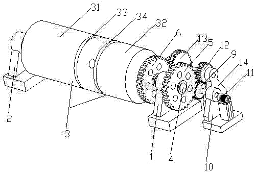
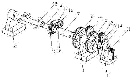
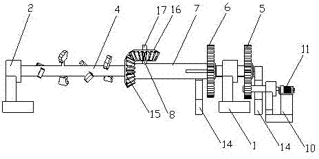
[0027] see Figure 1 to Figure 5 , the present invention is a drum-type metallurgical powder mixing device, which includes a base A1 and a base B2 that are oppositely arranged, a power mechanism that bridges between the base A1 and the base B2, and a drive mechanism that abuts the power mechanism, The transmission structure arranged on the output shaft of the power mechanism accommodates the output shaft of the power mechanism and the mixing bin 3 of the transmission structure. The inside of the mixing bin 3 is provided with a partition 33 that separates it into a mixing bin 31 and a transmission bin 32. An annular guide groove 34 is provided on the inner wall of the transmission chamber 32 .

[0028] The power mechanism includes a central transmission shaft 4 that runs through the base A1 and the top ring sleeve of the ba...


PUM


Abstract

The invention provides a roller type metallurgy powder mixing device, and belongs to the technical field of powder metallurgy mixing equipment. The roller type metallurgy powder mixing device has the beneficial effects that a mixing bin of the roller type metallurgy powder mixing device and a center transmission shaft of a stirring structure can rotate synchronously, and metallurgy powder is turned over and mixed; a transmission gear I on the center transmission shaft is driven by a driving gear, a hollow cylindrical rotating shaft is connected to the center transmission shaft in a transmission bin in a sleeving manner, rotation of a transmission gear II is achieved by means of the driving gear, a driven gear A and a driven gear B, and the aims that even though the transmission gear I and the transmission gear II are not coaxial, the transmission gear I and the transmission gear II can rotate synchronously, and stirring rods on the center transmission shaft fully stir powder particles are achieved; and diameter ratios of the powder particles are more balanced, and mixing is more sufficient.

Description

technical field [0001] The invention relates to the technical field of powder metallurgy mixing equipment, in particular to a drum-type metallurgical powder mixing device. Background technique [0002] Powder metallurgy is a process technology for producing metal or using metal powder (or a mixture of metal powder and non-metal powder) as raw material, forming and sintering to manufacture metal materials, composite materials and various types of products. Powder metallurgy has similarities with the production of ceramics. Therefore, a series of new powder metallurgy technologies can also be used for the preparation of ceramic materials. Due to the advantages of powder metallurgy technology, it has become the key to solve the problems of new materials and plays a pivotal role in the development of new materials. [0003] In the previous process of powder metallurgy, the mixing of metal powder is related to the quality of the subsequent metallurgical process. When mixing, var...

Claims


Application Information

Patent Timeline
IPC IPC(8): B22F9/04F16H1/20
CPCB22F9/04B22F2009/041F16H1/203
Inventor 胡海波唐馨尹雪峰于海青
Owner 深圳市泛海统联精密制造股份有限公司
Learn More