Extensible welding rod structure

A technology of welding rod and welding wire, applied in the field of sustainable welding rod structure, which can solve the problems of waste of welding rod, single function of welding rod, insufficient length, etc.

Inactive Publication Date: 2017-06-20
朱英
View PDF0 Cites 1 Cited by
  • Summary
  • Abstract
  • Description
  • Claims
  • Application Information

AI Technical Summary

Problems solved by technology

[0002] Welding rods are the most commonly used tools in the field of electric welding or gas welding, but the existing welding rods have a single function. During use, due to insufficient length or inconvenient use during welding, a lot of welding rods are wasted

Method used


Image

  • Extensible welding rod structure
  • Extensible welding rod structure
  • Extensible welding rod structure

Examples


Embodiment Construction

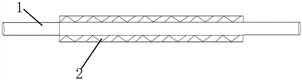
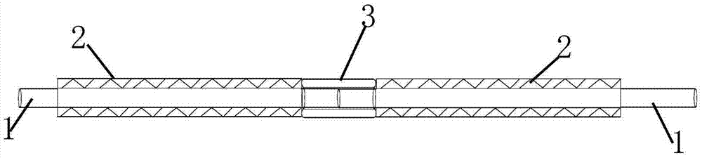
[0009] according to figure 1 — image 3 A continuous welding rod structure shown includes a main body of the welding rod and an interconnection device 3 , and is characterized in that the main body of the welding rod is composed of a welding wire 1 and a sheath 2 , and the welding wire 1 is wrapped with the sheath 2 .

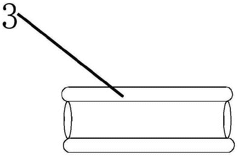
[0010] The interior of the interconnection device 3 is a hollow structure.

[0011] When using the present invention, the welding wire of welding rod can be penetrated in the interconnecting device, inserts another welding rod at the other end of interconnecting device then, so just can prolong the length of welding rod; The advantages of convenience and the ability to extend the length of the welding rod, and strong market economic value are worth promoting.


PUM


Abstract

The invention provides a continuous welding rod structure, which includes a welding rod main body and an interconnecting device, and is characterized in that the welding rod main body is composed of a welding wire and a sheath, and the welding wire is wrapped with the sheath. The invention has the advantages of simple structure, convenient use, and the ability to extend the length of the welding rod, has strong market economic value, and is worth popularizing.

Description

technical field [0001] The invention relates to a continuous welding rod structure. Background technique [0002] Welding rods are the most commonly used tools in the field of electric welding or gas welding, but the existing welding rods have a single function. During use, due to insufficient length or inconvenient use during welding, a lot of welding rods are wasted. Contents of the invention [0003] The invention provides a continuous welding rod structure, which includes a welding rod main body and an interconnection device, and is characterized in that the welding rod main body is composed of welding wire and a sheath, and the welding wire is wrapped with the sheath. [0004] The interior of the interconnection device is a hollow structure. [0005] When using the present invention, the welding wire of welding rod can be penetrated in the interconnecting device, inserts another welding rod at the other end of interconnecting device then, so just can prolong the leng...

Claims


Application Information

Patent Timeline
Patent Type & Authority Applications(China)
IPC IPC(8): B23K35/02
CPCB23K35/02
Inventor 不公告发明人
Owner 朱英
Why Eureka
Try Eureka