Compounding machine

A composite machine and frame technology, applied in the field of composite machines, can solve problems such as plate deformation and damage, and achieve the effect of avoiding deformation or damage and good winding effect

Active Publication Date: 2017-06-20
浙江铭凯集成房屋股份有限公司
View PDF5 Cites 4 Cited by
  • Summary
  • Abstract
  • Description
  • Claims
  • Application Information

AI Technical Summary

Problems solved by technology

[0004] In the above technical solution, when the motor drives the cutter to trim the edge, the friction between the cu

Method used


Image

  • Compounding machine
  • Compounding machine
  • Compounding machine

Examples


Embodiment Construction

[0028] The present invention will be described in further detail below in conjunction with the accompanying drawings.

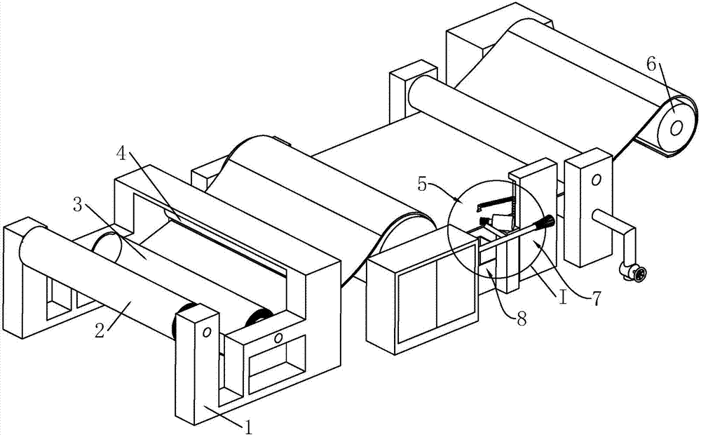
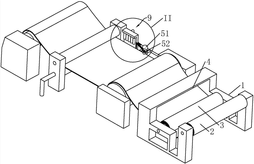
[0029] see figure 1 , a composite machine, comprising a frame 1, the front end of the frame 1 is provided with a sheet material unwinding mechanism 2, and the sheet material (such as a high-strength galvanized sheet) can be sleeved on the sheet material unwinding mechanism 2 and then realize unwinding through it; Next, a film unwinding mechanism 3 is provided. The film (such as a polymer film) can be sleeved on the film unwinding mechanism 3 and then unwinded through it. The film is located above the plate and is compounded by the composite mechanism 4 arranged behind. The compounding mechanism 4 includes two compounding rollers arranged on opposite sides. The compounding machine heats the compounding rollers. When the film and the plate pass through the two plates, they can be compounded, that is, the film is compounded on the plate.

[0030] see figure 1 ...


PUM


Abstract

The invention discloses a compounding machine. The compounding machine comprises a frame, a plate unwinding mechanism, a film unwinding mechanism, a compounding mechanism, an edge cutting mechanism and a winding mechanism, wherein the plate unwinding mechanism, the film unwinding mechanism, the compounding mechanism, the edge cutting mechanism and the winding mechanism are connected to the frame; a waste edge collecting mechanism is arranged on the edge cutting mechanism on the frame; a cooling circulation mechanism is also arranged on the edge cutting mechanism on the frame and comprises a liquid storage tank, a cooling liquid pipe and a liquid extracting mechanism; the liquid storage tank is fixedly connected to the frame and is located under the edge cutting mechanism; the cooling liquid pipe is provided with a nozzle facing the edge cutting mechanism; the liquid extracting mechanism is arranged between the liquid storage tank and the cooling liquid pipe. The compounding machine is simple in structure; the cooling circulation mechanism is used for cooling a part between a cutter and a plate, so that the deformation or damage of the plate caused by overhigh heat between the cutter and the plate can be avoided.

Description

technical field [0001] The invention relates to the technical field of plate coating equipment, in particular to a composite machine. Background technique [0002] The composite machine is to bond two or more layers of materials together with an adhesive. For example, film and cloth fiber or glass cloth are often used, and can be combined with paper, film, sponge, cloth, etc. [0003] A utility model with the notification number CN205521673U discloses an automatic edge trimming device for a compound machine, which includes a cutter and a motor, and the cutter and the motor are fixed on a vertical support; below the cutter is a horizontal support, and the horizontal The bracket is provided with a trimming recovery port, and a vertical recovery cylinder is connected with the trimming recovery port, and the vertical recovery cylinder is connected with a horizontal recovery cylinder; the end of the horizontal recovery cylinder is connected with a fan. [0004] In the above tec...

Claims


Application Information

Patent Timeline
IPC IPC(8): B32B37/00B32B38/10
CPCB32B37/0046B32B38/105
Inventor 王凯乐
Owner 浙江铭凯集成房屋股份有限公司
Why Eureka
Try Eureka