

Sand cushion isolation and shock absorption device for comprehensive pipe gallery and building method thereof
A technology of comprehensive pipe gallery and shock absorbing device, which is applied in protection devices, buildings, water conservancy projects, etc., can solve the problems of impracticality, unfavorable promotion and implementation, and high cost, and achieve excellent shock isolation and shock absorption effects, cheap and convenient materials, The effect of low cost
- Summary
- Abstract
- Description
- Claims
- Application Information
AI Technical Summary
Problems solved by technology
Method used
Image

Examples
Embodiment Construction
[0038] The present invention will be further described in detail below in conjunction with specific embodiments, which are explanations of the present invention rather than limitations.
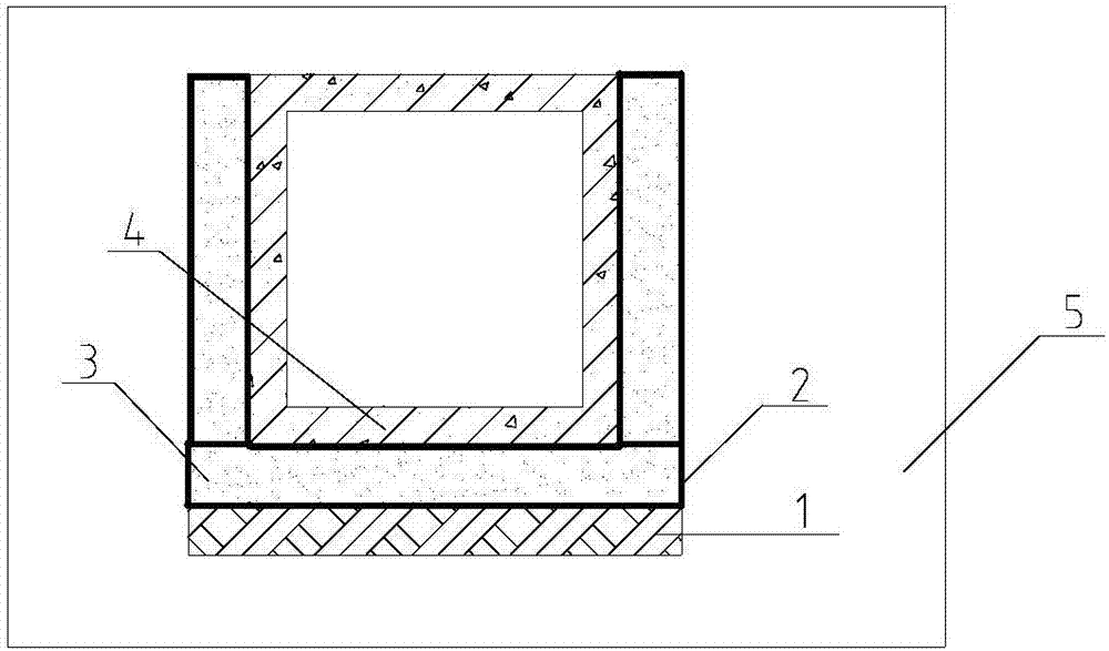
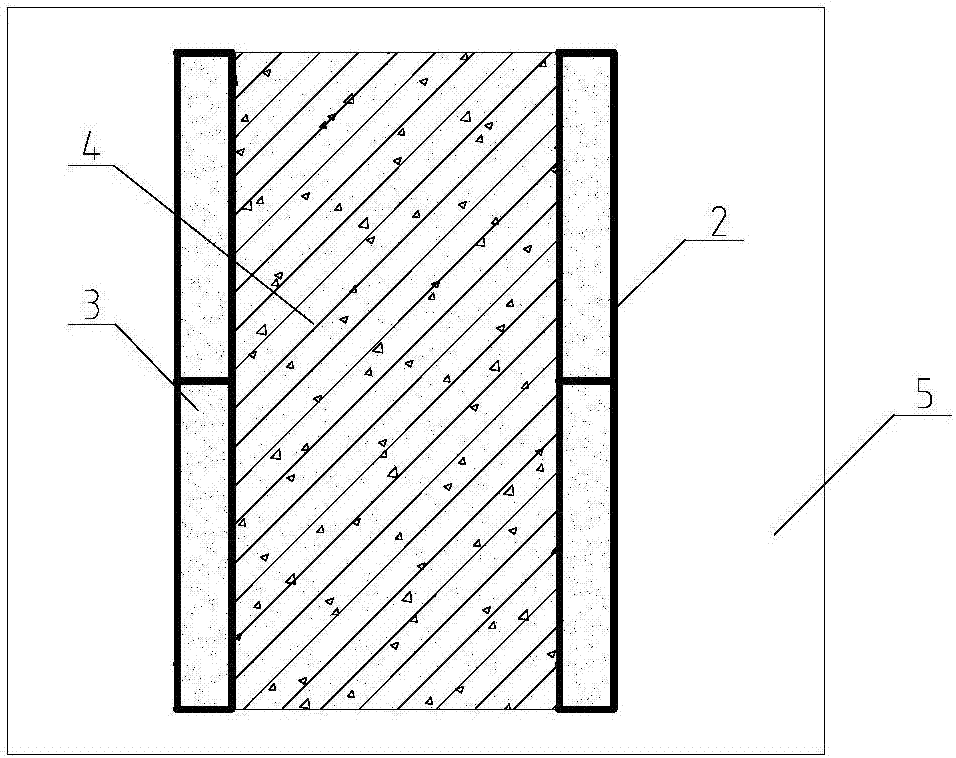
[0039] Specifically, such as figure 1 and figure 2 As shown, the sand cushion shock-isolation and shock-absorbing device of the comprehensive pipe gallery of the present invention includes a foundation shock-isolation and shock-absorbing device and a side wall shock-isolation and shock-absorbing device, wherein the comprehensive pipe gallery is buried in the formation 5 . The base shock-isolation and shock-absorbing device includes the base plate of the comprehensive pipe gallery 4, and the foundation base plate of the comprehensive pipe gallery 4 is provided with a foundation shock-isolation and shock-absorbing layer, and the foundation shock-isolation and shock-absorbing layer includes a geotechnical wrapping cloth 2 and coarse sand 3, the geotextile 2 wraps the coarse sand 3, and a compa...
PUM
| Property | Measurement | Unit |
|---|---|---|
| Thickness | aaaaa | aaaaa |
| Thickness | aaaaa | aaaaa |
| Particle size | aaaaa | aaaaa |
Abstract
Description
Claims
Application Information