
Automated device and method for supplying and discharging oil

A technology of oil unloading pipe and oil supply pump, which is applied in the field of machinery, can solve the problems of complex structure and inconvenient transportation of steam injection boilers in oil fields, and achieve the effects of easy relocation and transportation, easy operation, and avoiding airtightness

Active Publication Date: 2017-06-20
CHINA PETROLEUM & CHEM CORP +1
View PDF12 Cites 3 Cited by
  • Summary
  • Abstract
  • Description
  • Claims
  • Application Information

AI Technical Summary

Problems solved by technology

[0009] Aiming at the problems of complex structure and inconvenient transportation of oil field steam injection boilers in the prior art, the purpose of the present invention is to provide an automatic oil supply and unloading device and method with a more reasonable structure

Method used


Image

  • Automated device and method for supplying and discharging oil

Examples


Embodiment Construction

[0024] In order to make the technical problems, technical solutions and advantages to be solved by the present invention clearer, the following will describe in detail with reference to the drawings and specific embodiments.

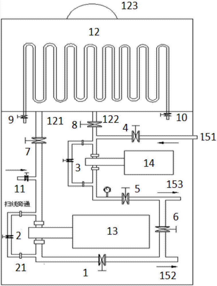
[0025] In order to solve the problem of complex structure of oilfield steam injection boilers in the prior art, the embodiment of the present invention proposes a figure 1 Shown is an automatic oil supply and unloading device for automatic oil supply, oil unloading, and line sweeping for steam injection boilers in oil fields, which includes: oil unloading tank 12, oil unloading pump 13, and oil supply pump 14;

[0026] Wherein the oil unloading tank 12 is provided with an oil unloading tank outlet 121 and an oil unloading tank inlet 122;

[0027] Wherein, the unloading pump 13 is provided with a first three-way, and the first three-way is connected to the outlet 121 of the oil unloading tank through the pipeline provided with the seventh valve 7, and con...


PUM


Abstract

The invention provides an automated device and method for supplying and discharging oil. The automated device for supplying and discharging the oil comprises an oil discharge tank, an oil discharge pump and an oil supply pump. The oil discharge tank is provided with an oil discharge tank outlet and an oil discharge tank inlet. The oil discharge pump is provided with a first tee junction. The first tee junction is connected with the oil discharge tank outlet through a pipeline with a seventh valve and is connected with an oil storage tank outlet through a first oil discharge pipeline with a first valve; the oil supply pump is provided with a second tee junction. The second tee junction is connected with the oil discharge tank inlet through a pipeline with an eighth valve and is connected with a burner outlet through a second oil discharge pipeline with a fifth valve; the oil storage tank inlet is connected with the oil discharge tank inlet through a pipeline with a fourth valve and the eighth valve The first oil discharge pipeline communicates with the second oil discharge pipeline through a communication pipeline with a sixth valve, and one end of the communication pipeline communicates with the first oil discharge pipeline between the first valve and the oil storage tank outlet, and the other end of the communication pipeline communicates with the second oil discharge pipeline between the fifth valve and the burner outlet.

Description

technical field [0001] The invention relates to the technical field of machinery, in particular to an automatic oil supply and unloading device. Background technique [0002] Thermal recovery of heavy oil is a mature oil recovery process in oilfields. Oilfield steam injection boilers are the key equipment for thermal recovery of heavy oil. The steam is injected into the developed oil layer to reduce the viscosity of the heavy oil, which is beneficial to the recovery of the heavy oil. [0003] Oilfield steam injection boilers, especially wet steam generators for oilfield fields, are more and more widely used, and there are dozens of corresponding auxiliary facilities. At present, the fuel system of steam injection boilers for oil field activities consists of oil unloading tanks, oil unloading pumps, oil storage tanks, and oil pump rooms. The main problems are as follows: [0004] One: There are many supporting facilities, which is not conducive to the flexibility of the ove...

Claims


Application Information

Patent Timeline
Patent Type & Authority Applications(China)
IPC IPC(8): E21B43/24
CPCE21B43/24
Inventor 张学超梁福元赵学展武八锁苗会清张勇王镪龙张玥文凤余刘建平王强赵云献张清波
Owner CHINA PETROLEUM & CHEM CORP
Learn More