
A fully automatic tunnel bolt installation equipment

A technology for installing equipment and tunnel anchors, which is applied to mining equipment, installation of bolts, and program-controlled manipulators. It can solve problems such as failure to meet construction schedule requirements, high manual installation costs, and failure to achieve anchor protection effects, etc., to achieve applicable geological conditions. The effect of wide range, fast installation speed and reduction of equipment failure rate

Active Publication Date: 2020-03-27
CHINA RAILWAY TUNNEL GROUP CO LTD
View PDF5 Cites 2 Cited by
  • Summary
  • Abstract
  • Description
  • Claims
  • Application Information

AI Technical Summary

Problems solved by technology

Using the drill arm to advance the installation of the anchor rod has the advantage of good installation effect, but its installation efficiency is low and cannot meet the schedule requirements; manual installation has the advantages of convenience and quickness, but during the installation process, the resistance is relatively large, and it is difficult to completely remove the anchor rod. Putting it into the anchor hole, workers often cut off the anchor directly, and the corresponding anchor protection effect cannot be achieved, and manual installation has the disadvantages of high cost and high risk
At present, there is no corresponding special equipment for tunnel bolt installation at home and abroad. Based on this, a fully automatic tunnel bolt installation manipulator is designed, which can realize convenient, fast, high-quality and automatic installation of tunnel bolts, and save construction costs.

Method used


Image

  • A fully automatic tunnel bolt installation equipment
  • A fully automatic tunnel bolt installation equipment
  • A fully automatic tunnel bolt installation equipment

Examples


Embodiment Construction

[0019] The present invention is further described in conjunction with accompanying drawing and specific embodiment:

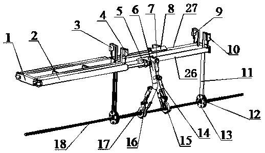
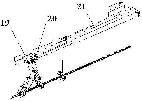
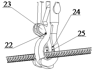
[0020] Such as Figure 1~3As shown, a fully automatic tunnel bolt installation equipment, the fully automatic tunnel bolt installation equipment has a bracket 1; the lower end of the bracket 1 is fixed with a guide rod 11 for guiding when installing the bolt; Described guide rod 11 is two that are arranged vertically to support, wherein a guide rod 11 is positioned at an end of support 1, and another guide rod 11 is fixed in the middle part of support; The lower end of described guide rod 11 is connected with detachable The guide rod wear plate 12, the middle part of the guide rod wear plate 12 has a through hole for the anchor rod 18 to pass through; the two sides of the bracket 1 are respectively provided with guide rails, namely guide rail I26 and guide rail II27; and the The above-mentioned guide rail I26 and guide rail II27 are located between the two gui...


PUM


Abstract

The invention belongs to the technical field of tunnel construction machines, and mainly relates to full-automatic tunnel anchor rod installing equipment. The full-automatic tunnel anchor rod installing equipment comprises a support (1). A guide rod (11) perpendicular to the support is fixed to the lower end of the support (1). The lower end of the guide rod (11) is connected with a guide rod abrasion-resistant plate (12), and a through hole for an anchor rod (18) to penetrate through is formed in the middle of the guide rod abrasion-resistant plate (12). A guide rail I (26) and a guide rail II (27) are arranged on two sides of the support (1) correspondingly. The guide rail I (26) is provided with a sliding block I (5). The guide rail II (27) is provided with a sliding block II (8). The full-automatic tunnel anchor rod installing equipment further comprises manipulators I and manipulators II used for grasping the anchor rod, and the manipulators I and manipulators II are arranged in a staggered mode. The full-automatic tunnel anchor rod installing equipment realizes mechanical assisted manual work, the anchor rod can be installed conveniently, rapidly and efficiently, and the installing of the tunnel anchor rod is realized.

Description

technical field [0001] The invention belongs to the technical field of tunnel construction machinery, and mainly relates to a fully automatic tunnel bolt installation device. Background technique [0002] Anchor protection operation is one of the key links in drilling and blasting tunnel construction, which has the characteristics of convenience, speed, safety and efficiency. In the process of anchor protection operation, bolt installation is an important part of it. There are two main operation methods for bolt installation. One is to install the bolt in the bolt hole by means of drill arm advancement, and the other is to manually install the bolt into the bolt hole. into the anchor hole. Using the drill arm to advance the installation of the anchor rod has the advantage of good installation effect, but its installation efficiency is low and cannot meet the schedule requirements; manual installation has the advantages of convenience and quickness, but during the installati...

Claims


Application Information

Patent Timeline
Patent Type & Authority Patents(China)
IPC IPC(8): E21D20/00B25J9/00B25J9/14
CPCB25J9/00B25J9/14E21D20/00
Inventor 刘瑞庆李大伟张迅周远航李剑雄陈义得杨露伟雷鸣孙海波张佳兴管羽
Owner CHINA RAILWAY TUNNEL GROUP CO LTD
Learn More