Control method for phase change heat storage heating system

A phase-change heat storage and heating system technology, applied in heating systems, heating methods, and central heating, can solve problems such as increasing the complexity of pipeline and equipment layout, and increasing equipment investment costs.

Active Publication Date: 2017-06-20
北京海房新能源科技有限公司
View PDF8 Cites 10 Cited by
  • Summary
  • Abstract
  • Description
  • Claims
  • Application Information

AI Technical Summary

Problems solved by technology

In this new type of use, in order to solve the problem of all-weather heating, two electric boilers need to be installed. During the heat storage process of the heat accumulator, one electric boiler provides heating for the outside, and

Method used


Image

  • Control method for phase change heat storage heating system
  • Control method for phase change heat storage heating system
  • Control method for phase change heat storage heating system

Examples


Embodiment 1

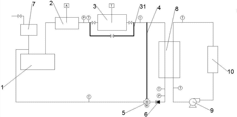
[0050] A phase change thermal storage heating system, including a heat supply cycle system, a load cycle system, heat exchange between the heat supply cycle system and the load cycle system through a heat exchange device 8; the heat supply cycle system includes an electric boiler 1, a heat supply cycle power device 2. Phase-change heat storage heat store 3, shunt pipe 4, the electric boiler 1, heat supply cycle power unit 2, phase-change heat storage heat store 3, and heat exchange device 8 are connected sequentially through heat supply cycle pipelines; 4 is set on the heat supply circulation pipeline and connected in parallel with the heat exchange device 8; the junction of the outlet pipe of the heat exchange device 8 and the branch pipe 4 is provided with a flow diverter regulator 5.

[0051] Wherein, the heat supply cycle system is used as a heat source system, and the heat is transferred to the load cycle system through the heat exchange device 8, and the load cycle system...

Embodiment 2

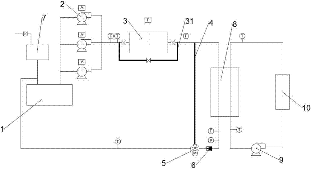
[0059] refer to Figure 2-3 , the heat supply cycle power device 2 has multi-stage output power, and is arranged between the electric boiler 1 and the phase change heat storage heat store 3. The heat supply cycle power device 2 includes at least two heating cycle tubes connected in parallel road pump assembly. This structure can adjust the total power output by the heating cycle power device 2 according to different electricity price periods and external temperature conditions by setting a heating cycle power device 2 with multi-stage output power, and provide cycle power that matches the system demand. Not only is it beneficial to reduce the operating cost of the heating system, but also in the heating process of the electric heating boiler 1, it prevents the boiler from bursting due to untimely circulation and heat accumulation in the electric heating boiler 1.

[0060] At the same time, when any pump assembly in the heating cycle power unit 2 is being maintained, in order ...

Embodiment 3

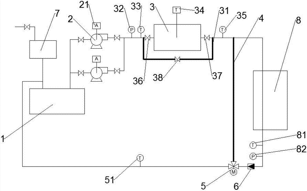
[0066] In order to realize the intelligent control of the entire system, multiple detection devices need to be installed in the system, specifically:

[0067] A heat supply and return water temperature detection device 81, a heat supply and return water pressure detection device 82, and a flow meter 6 are sequentially arranged on the heat supply circulation pipeline between the water outlet of the heat exchange device 8 and the flow divider 5 for measuring the supply and return water pressure. In the heat cycle system, the temperature, pressure and flow of the circulating water after heat exchange by the heat exchange device 8;

[0068] A mixed water temperature detection device 51 is provided on the heat supply circulation pipeline between the splitter regulator 5 and the electric boiler 1, which is used to measure the temperature of the circulating water after heat exchange through the heat exchange device 8 and the circulating water passed through the shunt pipe 4 after mixi...


PUM


Abstract

The invention discloses a control method for a phase change heat storage heating system. The phase change heat storage heating system comprises a central processing unit, a storage device, an electric heating boiler, a heat reservoir and a detection device. The central processing unit is connected with the electric heating boiler, the heat reservoir, the detection device and the storage device. The control method includes the following steps that firstly, heat storage is conducted on the heat reservoir through the electric heating boiler in the valley electricity time, heat release is conducted on the heat reservoir in the peak electricity time, and the rest of heat Qs of the electric heating boiler is calculated; secondly, the heat Qx needed in the period from the current time to the valley electricity starting time is estimated; and thirdly, whether Qs is smaller than Qx is judged, if the judgment result shows that Qs is smaller than Qx, the electric heating boiler is immediately started to store energy for the heat reservoir or store energy for the reservoir in the low-electricity-price time period, and if the judgment result shows that Qs is not smaller than Qx, the first step is executed. The whole phase change heat storage heating system is monitored, the starting time of the electric heating boiler can be elaborately controlled, when the heat of heat reservoir energy is insufficient for maintaining use of a user at a certain moment, heat storage and energy storage are conducted on the heat reservoir automatically in a relatively-ordinary-electricity-price time period or a valley-electricity-price time period.

Description

technical field [0001] The invention relates to the technical field of heating, in particular to a control method for a phase-change thermal storage heating system. Background technique [0002] According to the requirements of the National Development and Reform Commission, it is necessary to complete the transformation of more than 95% of the existing residential households in the country by the end of 2017, fully implement the peak-valley electricity price for residential electricity, and require the areas that have not yet introduced the peak-valley electricity price for residential electricity to issue policies before the end of 2015. Residents The user chooses to execute. That is, the power supply bureaus of all provinces and cities across the country will provide industrial, commercial and ordinary residents with a 50% discount on electricity prices from 23:00 to 7:00 the next morning to encourage nighttime electricity consumption, thereby improving the economic benef...

Claims


Application Information

Patent Timeline
IPC IPC(8): F24D19/10F24D11/00
CPCF24D11/004F24D19/1006F24D2200/08
Inventor 杨健韩玉瑞
Owner 北京海房新能源科技有限公司
Why Eureka
Try Eureka