
Method for measuring relationship between surveying coordinate system and prism coordinate system of star sensor

A technology for measuring coordinate systems and star sensors. It is used in measurement devices, surveying and navigation, instruments, etc. It can solve the problems of complex on-orbit correction, unclear deviation relationship, and deviation of measurement accuracy, and achieve high reliability and credibility. High degree and high implementability effect

Inactive Publication Date: 2017-06-20
SHANGHAI AEROSPACE CONTROL TECH INST
View PDF1 Cites 11 Cited by
  • Summary
  • Abstract
  • Description
  • Claims
  • Application Information

AI Technical Summary

Problems solved by technology

[0002] During the use of the star sensor, due to the unclear relationship between its prism coordinate system and the deviation relationship between the prism coordinate system, the measurement accuracy deviation relative to the three-axis attitude of the spacecraft needs to be corrected by on-orbit recalibration to eliminate the deviation. A series of problems such as large deviation of on-orbit data and complex on-orbit correction
It makes it difficult for users to confirm whether the error source comes from the error of the star sensor itself or the error caused by installing the star when using the product.

Method used


Image

  • Method for measuring relationship between surveying coordinate system and prism coordinate system of star sensor
  • Method for measuring relationship between surveying coordinate system and prism coordinate system of star sensor
  • Method for measuring relationship between surveying coordinate system and prism coordinate system of star sensor

Examples


Embodiment Construction

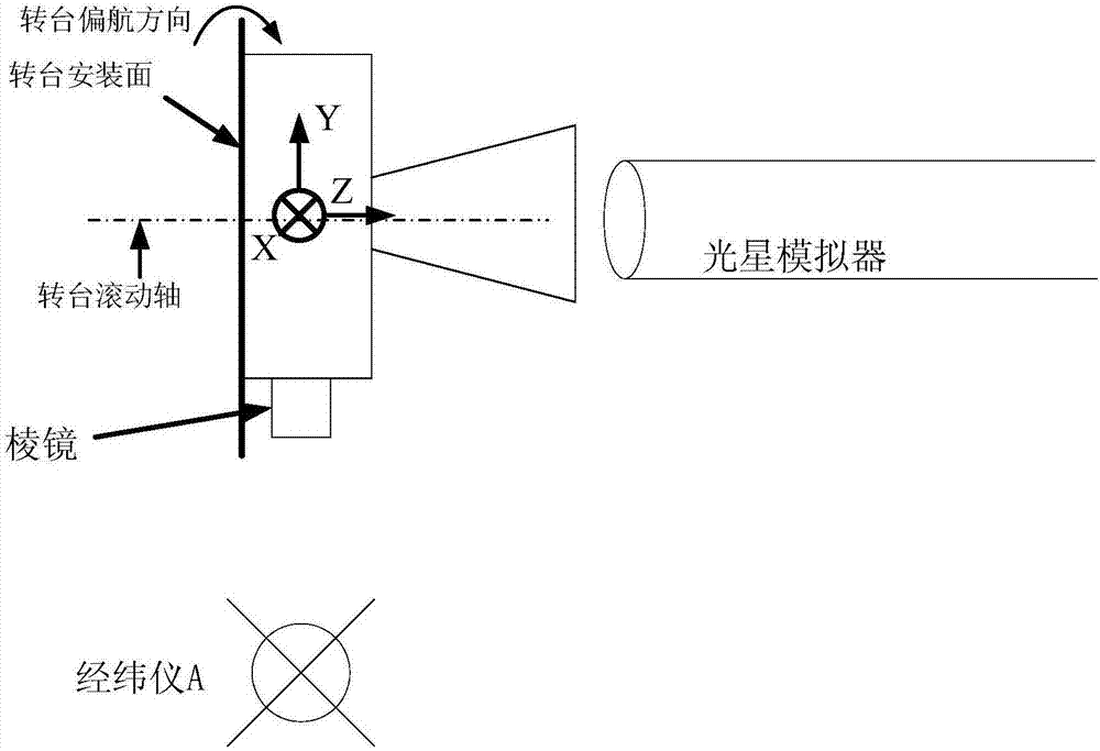
[0033] Such as figure 1 As shown, it is a schematic diagram of the test object of the present invention, and the star sensor includes: a prism, a detector and a housing. o 探测器 is the origin of the measuring coordinate system, X 探测器 is the X axis of the measurement coordinate system, Y 探测器 is the Y axis of the measuring coordinate system, Z 探测器 is the Z axis of the measuring coordinate system, O 棱镜 is the origin of the prism coordinate system, X 棱镜 is the X axis of the prism coordinate system, Y 棱镜 is the Y axis of the prism coordinate system, Z 棱镜 It is the Z axis of the prism coordinate system, and the three axes of the measurement coordinate system and the prism coordinate system point to the same direction, Z 探测器 is the detector optical axis of the star sensor, and the measurement coordinate system and the prism coordinate system of the star sensor satisfy the right-hand rule. The surface of the star sensor installed on the spacecraft or turntable is parallel to X ...


PUM


Abstract

The invention relates to a method for measuring a relationship between a surveying coordinate system and a prism coordinate system of a star sensor. According to the method, the star sensor is mounted on a high-precision three-axle turntable and is subjected to irradiating by using a photostar simulator, a deviation of a Z axis of the prism coordinate system of the star sensor relative to a Z axis of the surveying coordinate system is measured by using a theodolite, and meanwhile, a deviation of an X axis of the prism coordinate system of the star sensor relative to an X axis of the surveying coordinate system and a deviation of a Y axis of the prism coordinate system of the star sensor relative to a Y axis of the surveying coordinate system are measured by using two theodolites. According to the method, a surveying coordinate system and a prism coordinate system of a detector cover glass are correlated by means of light measurement, coordinate system relationship measurement is completed on the ground, and the measured deviations between the coordinate systems can be directly applied to entire star loading and the direct correction of in-orbit surveying coordinate systems of an attitude and orbit control system; the method is high in reliability, high in dependability and high in implementation performance, and the problems that in-orbit data deviation is large, in-orbit correction is complicated, and the like can be effectively reduced.

Description

technical field [0001] The invention belongs to the technical field of optical-mechanical-electrical integration, and in particular relates to a method for measuring the relationship between a star sensor measurement coordinate system and a prism coordinate system. Background technique [0002] During the use of the star sensor, due to the unclear relationship between its prism coordinate system and the deviation relationship between the prism coordinate system, the measurement accuracy deviation relative to the three-axis attitude of the spacecraft needs to be corrected by on-orbit recalibration to eliminate the deviation. There are a series of problems such as large deviation of on-orbit data and complex on-orbit correction. It makes it difficult for users to confirm whether the error source comes from the error of the star sensor itself or the error caused by installing the star when using the product. Contents of the invention [0003] The technical problem solved by ...

Claims


Application Information

Patent Timeline
IPC IPC(8): G01C25/00G01C21/02
CPCG01C25/00G01C21/025
Inventor 吴迪陈纾叶志龙郑循江王燕清
Owner SHANGHAI AEROSPACE CONTROL TECH INST
Learn More