A micro-injection tube

A technology of micro-injection and main part, which is applied in the field of injection tubes, can solve the problems of low injection precision and achieve the effects of low production cost, high injection precision and easy operation

Active Publication Date: 2020-01-17
BEIJING SDL TECH
View PDF8 Cites 0 Cited by
  • Summary
  • Abstract
  • Description
  • Claims
  • Application Information

AI Technical Summary

Problems solved by technology

[0004] The present invention aims to provide a new type of micro-injection tube to solve the problem of low sampling accuracy of existing injection tubes

Method used


Image

  • A micro-injection tube
  • A micro-injection tube
  • A micro-injection tube

Examples


Embodiment 1

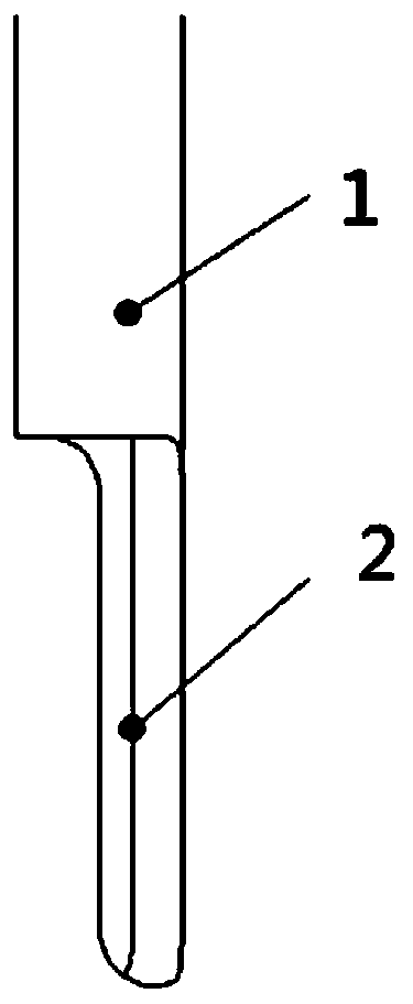
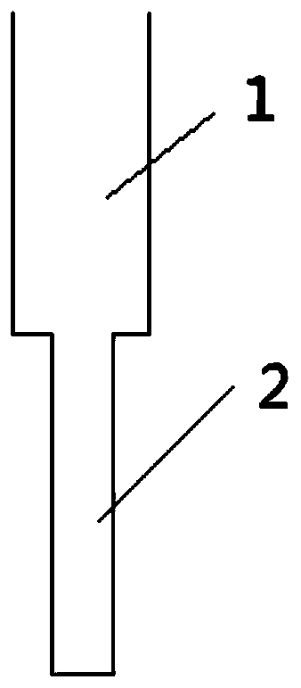
[0046]This embodiment provides a micro-injection tube, which includes a first connection part (not shown in the figure), a first body part (not shown in the figure), a second body part 1 and an immersion solution part 2. The structure of the second body part 1 and the immersion solution part 2 is as follows figure 1 , figure 2 and image 3 shown. The immersion solution part 2 is formed by extending the 1 / 4 pipe wall of the main body part, and the length of the immersion solution part 2 is 20mm. The main body part 1 is a hollow cylinder, Figure 4 is a cross-sectional schematic diagram of the main body part 1, its inner diameter is 4 mm, and its outer diameter is 7 mm. The end surface of the bottom end of the main body part 1 and the longitudinal section of the part immersed in the solution 2 are perpendicular to each other.

[0047] The first connecting portion is threadedly connected with the bottom end of the first body portion and the top end of the second body porti...

Embodiment 2

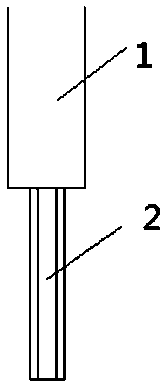
[0051] This embodiment provides a micro-injection tube, the structure of the micro-injection tube is as follows: Figure 6 As shown, it includes a main body part 1' and an immersion solution part 2'. The solution-immersed portion 2' is a cylinder having a diameter of 1.5 mm and a length of 20 mm. The main body 1' is a hollow cylinder with an inner diameter of 4 mm and an outer diameter of 7 mm. Such as Figure 6 As shown, the end surface of the bottom end of the main body part 1' is perpendicular to the longitudinal section of the immersed solution part 2'. Figure 7 It is a partial sectional view of the sampling tube of the present embodiment, as Figure 7 As shown, since the axis of the immersion solution part 2' in this embodiment is collinear with the center line of the pipe wall (the part between the inner wall and the outer wall) of the main part 1', the inner wall and the outer wall of the main part 1' are respectively aligned with The outer surfaces of the part imm...


PUM

PropertyMeasurementUnit
lengthaaaaaaaaaa
diameteraaaaaaaaaa

Abstract

The invention discloses a micro-sampling tube. The micro-sampling tube comprises a main body part and a solution immersion part, wherein the main body part is a hollow column body, and the inner boundary of the cross section of the main body part is circular; the end face of the bottom end of the main body part is vertical to the longitudinal cross section of the solution immersion part; the thickness of the solution immersion part is less than or equal to the that of a tube wall of the main body part. The micro-sampling tube provided by the invention has the advantages that the sampling accuracy is high, and a wall hanging phenomenon of a solution is avoided, thus being especially suitable for dripping the solution in a way of semi-drop or non-whole drop. Furthermore, by adopting the micro-sampling tube, low manufacturing cost, simple technology and convenient operation are realized.

Description

technical field [0001] The invention belongs to the field of sample injection tubes, in particular to a micro sample injection tube with high sample injection precision. Background technique [0002] The sampling tube is a commonly used instrument in chemical experiments. When the injection accuracy is high or the injection volume is small, the existing sampling tube cannot drop half a drop or the reagent that cannot be dropped due to gravity into the solution. , causing errors in the experimental data. Especially when the amount of reagent added is small, the error will have a greater impact on the experimental results. [0003] In order to solve the defects of the prior art and improve the sampling accuracy of the sampling tube, a new type of sampling tube needs to be developed. Contents of the invention [0004] The invention aims to provide a novel micro-injection tube to solve the problem of low sampling precision of the existing injection tube. [0005] The micro-...

Claims


Application Information

Patent Timeline
Patent Type & Authority Patents(China)
IPC IPC(8): G01N31/18
CPCG01N31/18
Inventor 敖小强肖林
Owner BEIJING SDL TECH
Why Eureka
Try Eureka