Variable-stiffness flexible bionic fish model based on internal fluid pressure adjustment

A fluid pressure and variable stiffness technology, applied in the field of underwater bionic robots, can solve problems such as large turning radius, lower propulsion efficiency than real fish, and adjustment of fish tail stiffness

Inactive Publication Date: 2017-06-20
HARBIN INST OF TECH
View PDF5 Cites 7 Cited by
  • Summary
  • Abstract
  • Description
  • Claims
  • Application Information

AI Technical Summary

Problems solved by technology

However, this structure cannot meet the flexibility of the robot fish in the water, the turning radius is too large, and it is difficult to adjust the stiffness of t...

Method used


Image

  • Variable-stiffness flexible bionic fish model based on internal fluid pressure adjustment
  • Variable-stiffness flexible bionic fish model based on internal fluid pressure adjustment
  • Variable-stiffness flexible bionic fish model based on internal fluid pressure adjustment

Examples


Embodiment 1

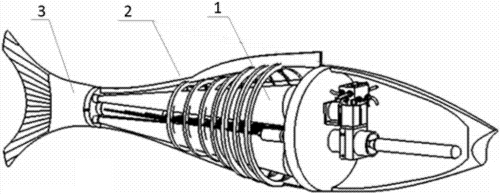
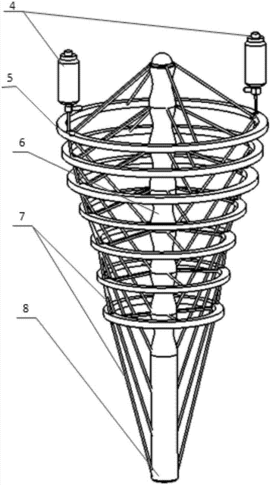
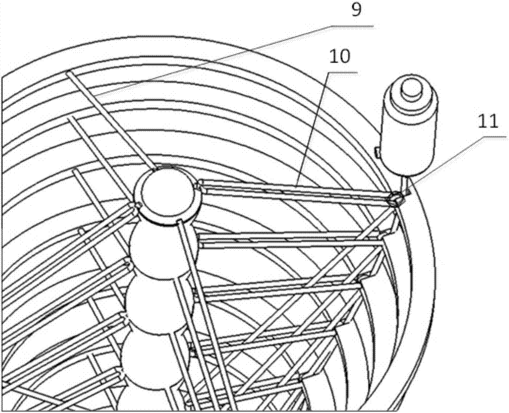
[0021] Such as Figure 1-4 As shown, a flexible bionic fish model with variable stiffness based on internal fluid pressure adjustment, including fish head, fish body 2 and caudal fin 3, the fish head and fish body are wrapped with skin, and the fish head is equipped with aerodynamic power Control unit; the fish body includes four internal conical pneumatic muscles 1 and nested series-parallel units, the nested series-parallel units serve as the spine and skeleton of the bionic fish, and the four internal conical pneumatic muscles 1 are respectively located in the nested Inside the series-parallel unit, the front end of each internal conical aerodynamic muscle 1 is connected to the fish head, and its end is connected to the tail fin through a rigid fixture. The aerodynamic power control unit is connected to the nested series-parallel unit and four internal conical muscles The pneumatic muscle is connected, and the pneumatic power control unit realizes the swing and twist of the...

Embodiment 2

[0028] Such as figure 1 , 4 Shown, present embodiment comprises three parts of fish head, fish body and tail. The fish body is the main moving part. The tail, as the end effector, is a crescent piece made of hard plastic, and the selection of geometric parameters is as close as possible to the size of the tail fin of a fish in reality. One end of the rigid fixture 12 is connected with the conical pneumatic muscle 1 , and the other end of the rigid fixture 12 is connected with the crescent-shaped plastic plate 3 .

[0029] Such as Figure 5-7 As shown, there is a pneumatic power control unit in the head of the fish, which is used as the power source of the whole fish, including power supply, suction pipe, diverter, air pipe, exhaust valve, proportional control valve, mechanical calibrator, and air storage tank. The structure refers to the arrangement of pneumatic components of robotic fish in the article "Autonomous Soft Robotic Fish Capable of Escape Maneuvers Using Fluidi...


PUM


Abstract

The invention provides a variable-stiffness flexible bionic fish model based on internal fluid pressure adjustment. The model comprises a fish head portion, a fish body and a tail fin. A pneumatic power control unit is installed in the fish head portion. The fish body comprises four internal taper pneumatic muscles and a nested series-parallel unit. The nested series-parallel unit is taken as a spine and a skeleton of a bionic fish. The four internal taper pneumatic muscles are located in the nested series-parallel unit respectively. A front end of each internal taper pneumatic muscle is connected to the fish head portion, and a tail end is connected to the tail fin through a rigid fixing component. The pneumatic power control unit is connected to the nested series-parallel unit and the four internal taper pneumatic muscles respectively. The pneumatic power control unit adjusts an internal intensity of pressure of the internal taper pneumatic muscles so as to realize fish body swinging and torsion or changes an average intensity of pressure so that rigidity of a tail portion of the fish body changes. The model is flexible, according to a swimming speed, tail portion rigidity can be adjusted and the model is energy-saving and high-efficient.

Description

technical field [0001] The invention mainly relates to the field of underwater bionic robots, in particular to a flexible bionic fish model with variable stiffness based on internal fluid pressure regulation. Background technique [0002] The current research on the swimming mechanism of BCF fish shows that: 1. There is muscle tissue attached to the spine of the fish, which drives the fish tail to swing in the water, generating an inverse Karman vortex street, and uses the reaction force generated by it to push the fish body forward; 2. The fish tail Four large muscle groups are distributed around part of the spine. When the fish swims, it adjusts its own tension to change the stiffness of the fish tail. Because different swimming speeds require different stiffnesses, the natural frequency of the body and the swing frequency of the tail can reach the same level. 3. The four muscle groups around the spine can bend themselves in all directions by contracting the fish tail, gen...

Claims


Application Information

Patent Timeline
IPC IPC(8): G09B23/36
CPCG09B23/36
Inventor 姜洪洲陈巍巍
Owner HARBIN INST OF TECH
Why Eureka
Try Eureka