Supporting method of motion platform of machine tool

A technology of motion platform and support method, which is applied in the direction of metal processing machinery parts, measuring/indicating equipment, drilling/drilling equipment, etc., and can solve the problems that affect the life of guide rail sliders, long suspension sections, unevenness, etc. that affect the motion performance

Inactive Publication Date: 2011-04-27
HANS LASER TECH IND GRP CO LTD +1
View PDF3 Cites 8 Cited by
  • Summary
  • Abstract
  • Description
  • Claims
  • Application Information

AI Technical Summary

Problems solved by technology

For multi-axis synchronous drilling technology, a moving platform is generally installed on the base frame through a support system, and a beam is arranged on the frame, and multiple drill bits can be installed at intervals on the beam. However, there is a problem with the dual guide rail structure: due to the long span of the motion platform, it is easy to cause long overhanging sections on both sides of the main rail slider after positioning, which in turn leads to insufficient mechanical stiffness at the overhanging section, which is easy to cause The whole working platform starts to vibrate
[0003] The first method is to replace the double guide rail structure with four guide rails, that is, add a pair of auxiliary guide rails parallel to the main guide rail under the overhanging section for support. Although this method can well solve the problem caused by the large span However, in actual use, the four guide rails will have defects in motion performance: because the ideal parallel state of the four guide rails and the uniform distribution of the force on the guide rail slider are very difficult to achieve, this will easily cause the motion platform to slide between the guide rails Mutual interference and uneven force will be generated, which will affect the motion performance and the life of the guide rail slider, and the use of four guide rails will bring additional assembly and maintenance costs

Method used


Image

  • Supporting method of motion platform of machine tool
  • Supporting method of motion platform of machine tool
  • Supporting method of motion platform of machine tool

Examples


Embodiment Construction

[0023] In order to further illustrate the principle and structure of the present invention, preferred embodiments of the present invention will now be described in detail with reference to the accompanying drawings.

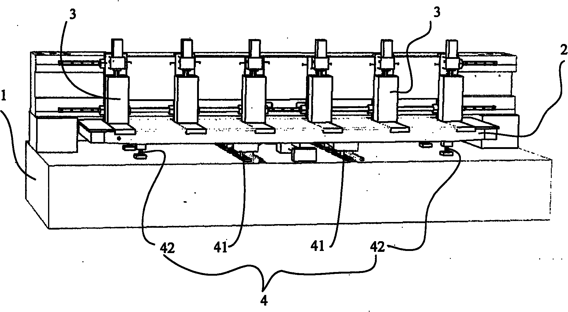
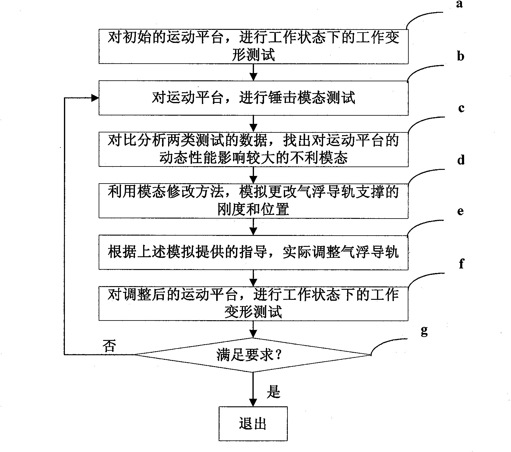
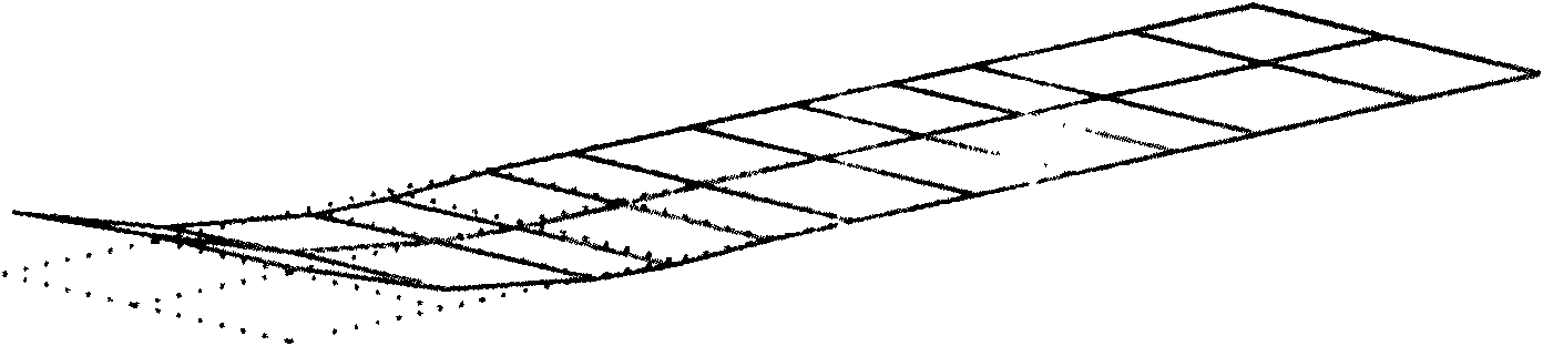
[0024] The supporting method of the motion platform of the machine tool of the present invention is: apply the vibration analysis theory to carry out the position layout and rigidity selection of the air-floating guide rail support of the motion platform of the machine tool, use the vibration test means to carry out the modal analysis and the work deformation analysis of the motion platform, and aim at the working process In order to solve the deformation problem of the motion platform, the position and stiffness of the air bearing guide rail support are improved by using the modal modification method, so as to realize the adjustment of the dynamic characteristics of the motion platform.

[0025] see figure 2 As shown, the supporting method of the machine tool m...


PUM


Abstract

The invention relates to a supporting method of a motion platform of a machine tool. A process for determining the rigidity and the position of an air-floating guide rail in a support system comprises the following steps of: a, testing the work deformation of an initial motion platform under a work state; b, testing a hammer mode of the motion platform; c, comparing and analyzing data of two tests and finding an adverse mode which has larger effect on the dynamic property of the motion platform; d, simulating and changing the rigidity and the position of an air-floating guide rail support by using a mode modifying method; e, practically regulating the air-floating guide rail according to a direction supplied by the simulation; f, testing the work deformation of the regulated motion platform under the work state; and g, judging whether the regulated motion platform satisfies requirements, if so, quitting, and otherwise, returning the step b to circulate. The invention can ensure that the integral rigidity and the anti-vibration ability of the motion platform satisfy requirements.

Description

technical field [0001] The invention relates to a machine tool, in particular to a supporting method for a motion platform in the machine tool. Background technique [0002] In the large-scale industrial production of assembly line operation, the multi-axis CNC PCB (printed circuit board) drilling machine that can improve the processing and production efficiency is the development trend of today's CNC drilling machine. For multi-axis synchronous drilling technology, a moving platform is generally installed on the base frame through a support system, and a beam is arranged on the frame, and multiple drill bits can be installed at intervals on the beam. However, there is a problem with the dual guide rail structure: due to the long span of the motion platform, it is easy to cause long overhanging sections on both sides of the main rail slider after positioning, which in turn leads to insufficient mechanical stiffness at the overhanging section, which is easy to cause The whol...

Claims


Application Information

Patent Timeline
Patent Type & Authority Applications(China)
IPC IPC(8): B23Q17/00B23B41/02
Inventor 崔彦洲宋福民李宁邹海天高云峰
Owner HANS LASER TECH IND GRP CO LTD
Why Eureka
Try Eureka