
A LED packaging method based on phosphor powder uniform coating

A technology of LED packaging and phosphor powder, which is applied in the direction of semiconductor devices, electrical components, circuits, etc., can solve the problems of difficult mixing of phosphor powder and packaging glue, wide range of particle sizes, inconsistent particle sizes of phosphor powder, etc., to reduce Equipment requirements and operation difficulty, improving the economic benefits of the enterprise, and improving the effect of particle size consistency

Active Publication Date: 2019-01-29
WUHU JUFEI PHOTOELECTRIC TECH CO LTD
View PDF7 Cites 0 Cited by
  • Summary
  • Abstract
  • Description
  • Claims
  • Application Information

AI Technical Summary

Problems solved by technology

However, due to the inconsistent particle size of different types of phosphors; even for the same phosphor, the particle size distribution is not uniform (the particle size distribution range is large, and the size of the phosphor particles is inconsistent)
However, if the particle size of the phosphor powder is inconsistent, or the range of particle size is too wide, it is difficult to mix the phosphor powder and the encapsulation glue evenly.
Uneven mixing will lead to the same volume of fluorescent glue injected into each LED when dispensing glue, but the amount of phosphor powder in the actual fluorescent glue will be different. At the same time, it is difficult to achieve uniform coating of phosphor powder in the bracket
Finally, during mass production, due to the difference in the amount of phosphor powder, the actual brightness and color of the packaged LED products will change, thereby reducing the output concentration of mass production

Method used


Image

  • A LED packaging method based on phosphor powder uniform coating
  • A LED packaging method based on phosphor powder uniform coating
  • A LED packaging method based on phosphor powder uniform coating

Examples


Embodiment 1

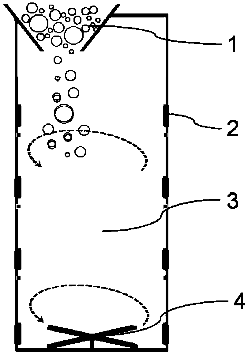
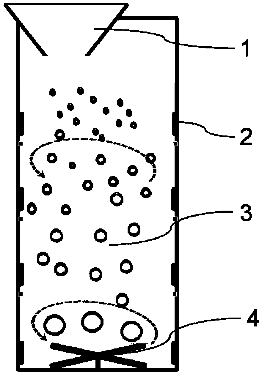
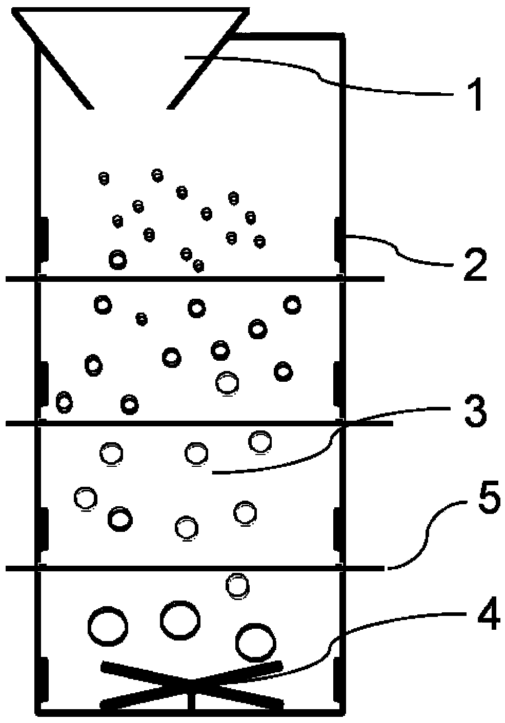
[0044] Embodiment 1 This embodiment discloses a LED packaging method based on uniform coating of phosphor powder (for details, see Figure 1-11 shown), the process steps of the method are as follows:

[0045] 1) Firstly, phosphor powder is screened by a particle size screening device for phosphor powder. A feeding port 1 is provided on the top of the screening device, and an accommodating chamber 3 filled with a dispersion solution is provided inside the device. The feeding port 2 Connected with the accommodating chamber 3, a stirring rotor 4 is provided at the bottom of the accommodating chamber 2; at least one receiving partition 5 is arranged on the outer wall of the device; the receiving partition 5 is connected with the accommodating chamber The bottom of 3 is parallel.

[0046] According to the different falling speeds of phosphors with different particle sizes (weights) in the dispersion liquid, the solution mixed with phosphors is isolated according to the height, so ...

Embodiment 2

[0059] Embodiment 2 This embodiment discloses a LED packaging method based on phosphor powder uniform coating, and the process steps of the method are as follows:

[0060] 1) Firstly, phosphor powder is screened by a particle size screening device for phosphor powder. A feeding port 1 is provided on the top of the screening device, and an accommodating chamber 3 filled with a dispersion solution is provided inside the device. The feeding port 2 Connected with the accommodating chamber 3, a stirring rotor 4 is provided at the bottom of the accommodating chamber 2; at least one receiving partition 5 is arranged on the outer wall of the device; the receiving partition 5 is connected with the accommodating chamber The bottom of 3 is parallel.

[0061] According to the different falling speeds of phosphors with different particle sizes (weights) in the dispersion liquid, the solution mixed with phosphors is isolated according to the height, so as to realize the screening of the par...

Embodiment 3

[0074] Embodiment 3 This embodiment discloses a LED packaging method based on phosphor powder uniform coating, and the process steps of the method are as follows:

[0075] 1) A liquid-phase fluorescent powder particle size screening device, including a feed inlet, a drying vent, a dispersion solution, a stirring rotor, and a receiving partition. The stirring rotor is placed in the dispersion solution, and each drying vent is With socket. According to the different falling speeds of phosphors with different particle sizes (weights) in the dispersion liquid, the solution mixed with phosphors is isolated according to the height, so as to realize the screening of the particle size of phosphors. The dispersion solution is an inorganic and organic solution of water, dichlorobenzene, and ethylene glycol monomethyl ether, and the number of drying vents is 13.

[0076] 2) Inject an appropriate amount of dispersion solution into the sieving device, and then take an appropriate amount o...


PUM


Abstract

The invention relates to the field of LED packaging, and specifically relates to an LED packaging method based on uniform coating of fluorescent powder. The LED packaging method comprises the steps of firstly screening the fluorescent powder by adopting a fluorescent powder particle diameter screening device, wherein the top of the screening device is provided with a material inlet port, the screening device is internally provided with an accommodating cavity filled with a dispersed solution, the material inlet port port is connected with the accommodating cavity, and the bottom of the accommodating cavity is provided with a stirring rotor; the outer wall of the screening dev ice is provided with at least one material receiving partition board; and the material receiving partition board is parallel to the bottom of the accommodating cavity. The screening device and the packaging method are simple to operate and applicable to mass industrial operations. The consistency of the fluorescent powder in particle diameter is improved, the fluorescent powder is easy to be uniformly mixed with packaging glue, and equipment requirements and the operation difficulty of a glue stirring process are reduced; and the output concentration ratio of acquired LEDs is improved, the delivery rate is improved, and the economic benefit of enterprises can be significantly improved.

Description

technical field [0001] The invention relates to the field of LED packaging, in particular to an LED packaging method based on uniform coating of fluorescent powder. Background technique [0002] Compared with traditional light sources, light-emitting diodes (LEDs) have many advantages such as high color rendering (high color gamut, high color rendering index), high brightness, long life, energy saving and environmental protection, real-time color control, shock and vibration resistance, etc. Rapid development. In the entire LED industry chain, LED packaging is a crucial link. The current LED packaging process mainly includes processes such as die bonding, wire bonding, glue dispensing, light splitting, and packaging. Among them, the glue dispensing process is to first mix the fluorescent powder with the packaging glue to form a fluorescent glue, and then inject the fluorescent glue into the LED bracket to protect the chips and bonding wires in the bracket. In addition to ...

Claims


Application Information

Patent Timeline
Patent Type & Authority Patents(China)
IPC IPC(8): H01L33/00H01L33/50H01L33/52
CPCH01L33/005H01L33/504H01L33/52
Inventor 张志宽邢其彬
Owner WUHU JUFEI PHOTOELECTRIC TECH CO LTD
Learn More