A smart microgrid node layout method in an area

A layout method and micro-grid technology, applied in the field of power system, to achieve the effect of easy implementation, simplified connection relationship, and simplified cumbersome degree

Inactive Publication Date: 2019-05-10
国网山东省电力公司平度市供电公司
View PDF6 Cites 0 Cited by
  • Summary
  • Abstract
  • Description
  • Claims
  • Application Information

AI Technical Summary

Problems solved by technology

[0005] In view of the above problems, the present invention discloses a method for layout of smart microgrid nodes in an area, which can uniquely determine the layout of these smart microgrid nodes in the area occupied by traditional power grids by using the connection relationship between smart microgrids, And under this layout, the area covered by each microgrid is basically the same, which effectively avoids the problem that a certain microgrid is damaged due to excessive load

Method used


Image

  • A smart microgrid node layout method in an area
  • A smart microgrid node layout method in an area
  • A smart microgrid node layout method in an area

Examples


specific Embodiment 1

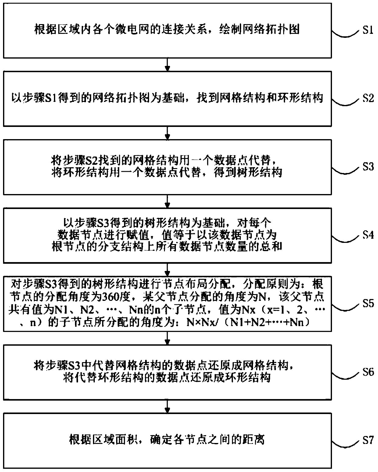
[0029] The flow chart of the node layout method of the smart microgrid in the region in this embodiment is as follows figure 1 shown. The smart microgrid node layout method in this area includes the following steps:

[0030] S1. Draw a network topology diagram according to the connection relationship of each microgrid in the region;

[0031] S2. Based on the network topology diagram obtained in step S1, find a grid structure and a ring structure;

[0032] S3. The grid structure found in step S2 is replaced by a data point, and the ring structure is replaced by a data point to obtain a tree structure;

[0033] S4. Based on the tree structure obtained in step S3, assign a value to each data node, and the value is equal to the sum of the numbers of all data nodes on the branch structure with the data node as the root node;

[0034] S5. Perform node layout allocation on the tree structure obtained in step S3. The allocation principle is: the allocation angle of the root node is...

specific Embodiment 2

[0037] The node layout method of the smart microgrid in the region of this embodiment is further limited on the basis of the specific embodiment 1: the leaves of the tree structure are peeled off sequentially, if:

[0038] There is only one data node left, which serves as the root node;

[0039] There are two remaining data nodes, and any one of the data nodes serves as the root node.

[0040] Let's take a set of data as an example to further describe the above two embodiments in detail:

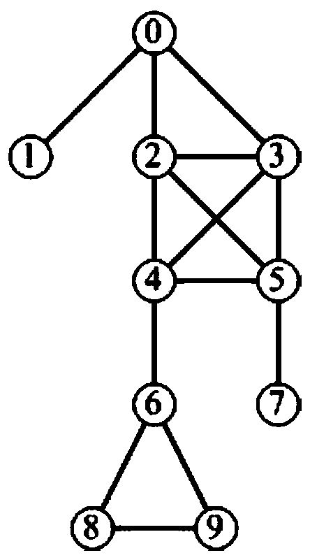
[0041] S1. According to the connection relationship of each microgrid in the region, draw a network topology map, such as figure 2 shown.

[0042] S2. Based on the network topology diagram obtained in step S1, a grid structure and a ring structure are found; wherein, 0 nodes, 2 nodes, 3 nodes, 4 nodes and 5 nodes form a grid structure, and 6 nodes, 8 nodes and 9 nodes The nodes form a ring structure.

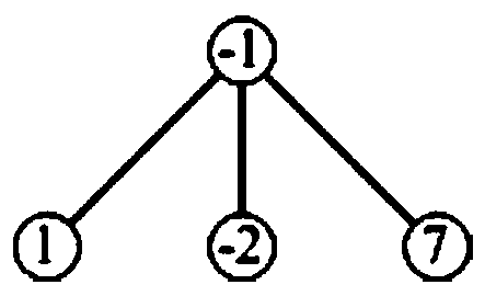
[0043] S3. The grid structure found in step S2 is replaced by a data point, and the r...


PUM


Abstract

The invention belongs to the technical field of electric power systems and specifically relates to an intra-region intelligent micro-grid node layout method which comprises the following steps: a network topological graph is drawn according to a connection relation among all micro-grids in a region, grid structures and annular structures are found, each of the grid structures and annular structures is replaced with a data point, a tree structure is obtained, a value is assigned to each data node, node layout distribution is performed after value assigning operation, data points replacing the grid structures and the annular structures are restored to the annular structures, and distance among all nodes is determined according to area of the region. Via use of the intra-region intelligent micro-grid node layout method, the connection relation among the intelligent micro-grids can be used for uniquely determining layout of the intelligent micro-grid nodes in a region occupied by a traditional power grid, all micro-grids are roughly consistent in terms of occupation area in the layout, and a problem that a certain micro-grid is overloaded and therefore damaged can be effectively prevented.

Description

technical field [0001] The invention belongs to the technical field of electric power systems, and in particular relates to a node layout method of an intelligent micro-grid in a region. Background technique [0002] Micro-Grid refers to a small power generation and distribution system composed of distributed power sources, energy storage devices, energy conversion devices, loads, monitoring and protection devices, etc. Microgrid is an autonomous system capable of self-control, protection and management, which can be connected to the external grid or run in isolation. The emergence of microgrid can realize the flexible and efficient application of distributed power, and solve the problem of grid connection of distributed power with a large number and various forms. [0003] The combination of microgrid and artificial intelligence technology forms a smart microgrid, which can also form new technical advantages on the basis of traditional microgrid technology. At present, the...

Claims


Application Information

Patent Timeline
Patent Type & Authority Patents(China)
IPC IPC(8): H02J3/00
CPCH02J3/00H02J2203/20Y02P80/14
Inventor 刘义荆宝平杨少华温丽华潘清涛焦丽娜潘麟官家琳焦红涛李海生
Owner 国网山东省电力公司平度市供电公司
Why Eureka
Try Eureka