Lighting power generation device for achieving solar full-spectrum utilization by condensation light split technology

A technology of a power generation device and a solar cell, applied in the field of solar energy, can solve the problems of waste of resources, low utilization rate of solar energy, and damage to optical fibers, and achieve the effects of avoiding damage to optical fibers, realizing full spectrum utilization, and prolonging service life.

Inactive Publication Date: 2017-06-20
HUBEI UNIV OF TECH
View PDF6 Cites 6 Cited by
  • Summary
  • Abstract
  • Description
  • Claims
  • Application Information

AI Technical Summary

Problems solved by technology

[0003] At present, although the solar fiber optic lighting devices proposed at home and abroad can realize indoor lighting, there are more or less shortcomings such as large errors, poor stability, and non-automatic sun tracking in the actual application process, and most systems use the sun Light is directly introduced into the lighting place, and the solar spectrum that can be perceived by ordinary human vision is the visible light band of 380nm~760nm, accounting for about 50% of the solar radiant energy. Ordinary lighting only needs to meet the visible light spectrum range; A large amount of extreme infrared light (the solar spectrum is greater than 760nm) is wasted, which is equivalent to the loss of about 43% of the solar radiant energy. The full spectrum utilization of sunlight has not been realized, resulting in low utilization of solar energy and resource loss. waste of
Moreover, infrared light has the characteristics of high heat and strong penetrating ability, and it will damage the optical fiber to a certain extent when it is transmitted in the optical fiber.

Method used


Image

  • Lighting power generation device for achieving solar full-spectrum utilization by condensation light split technology
  • Lighting power generation device for achieving solar full-spectrum utilization by condensation light split technology
  • Lighting power generation device for achieving solar full-spectrum utilization by condensation light split technology

Examples


Embodiment Construction

[0015] In order to facilitate those of ordinary skill in the art to understand and implement the present invention, the present invention will be described in further detail below in conjunction with the accompanying drawings and embodiments. It should be understood that the implementation examples described here are only used to illustrate and explain the present invention, and are not intended to limit this invention.

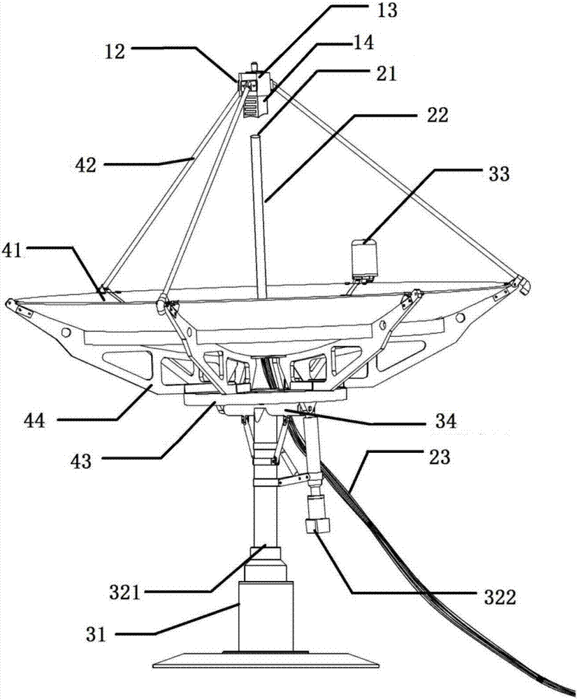
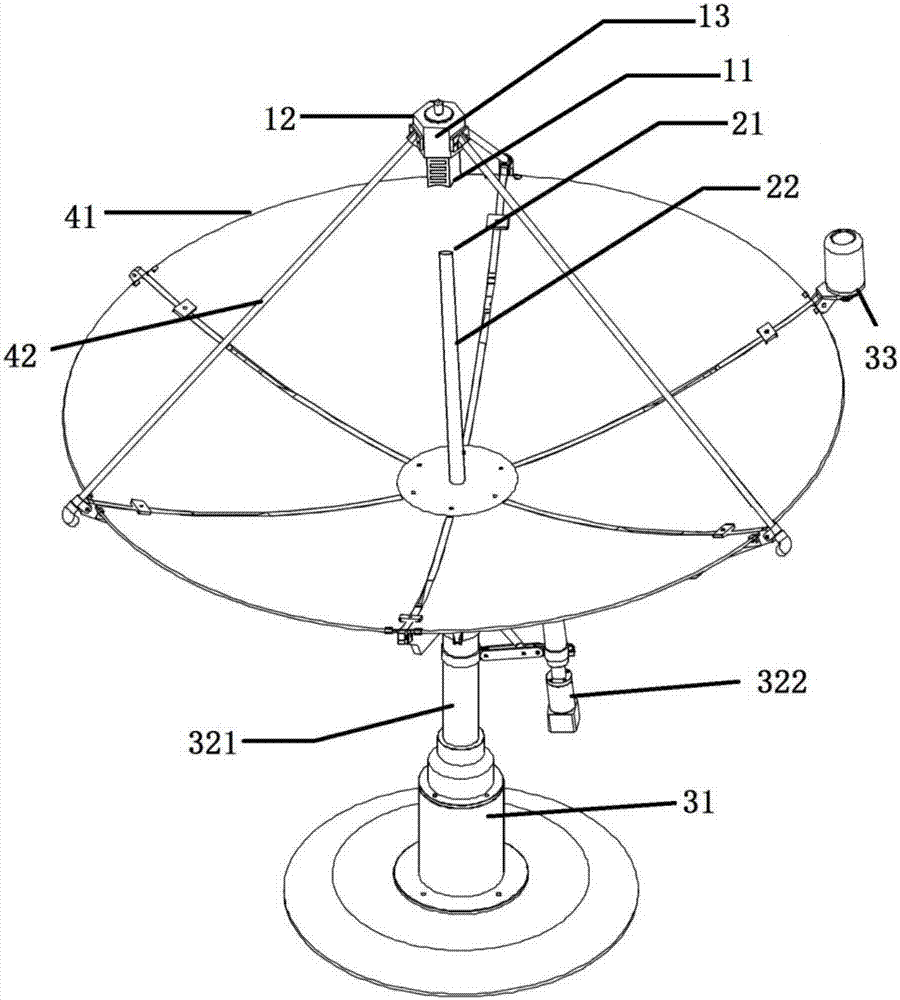
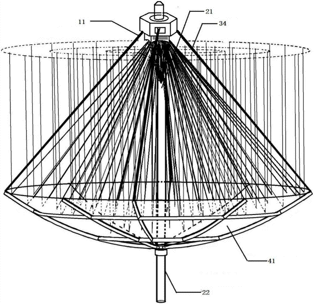
[0016] The purpose of the present invention is to provide a dish-type concentrating-splitting optical fiber hybrid lighting power generation scheme. By introducing light-splitting technology and automatic sun-tracking technology, the sunlight is always vertically incident on the dish-type concentrating mirror surface, and converges to the focal point through the dish surface. On the spectroscopic sheet below, the spectroscopic sheet separates infrared light and visible light. The transmitted infrared light is generated and stored by the solar cell behind the s...


PUM


Abstract

The invention discloses a lighting power generation device for achieving solar full-spectrum utilization by a condensation light split technology. The lighting power generation device comprises a light split unit, an optical fiber lighting unit, an automatic control sun-chasing unit and a disc-type condensation unit, wherein the light split unit is arranged at a focusing point of the disc-type condensation unit and is used for coupling reflected light to a position of an optical fiber, the automatic control sun-chasing unit is arranged on a disc surface of the disc-type condensation unit and is used for controlling the device to rotate with sun and making sunlight perpendicularly incident to a disc-type condensation mirror surface of the disc-type condensation unit all the time, the sunlight is converged on the light split unit at the focusing point by the disc-type condensation mirror surface, the optical fiber lighting unit is arranged under the light split unit, the light split unit is used for separating infrared light from visible light, power is stored and provided for rotation of the whole device by the transmitting infrared light through a solar cell behind the light split unit, and reflected visible light is guided to the indoor for lighting by the optical fiber lighting unit. By the lighting power generation device, the full-spectrum utilization of solar spectrum is achieved, and the sunlight utilization ratio is improved.

Description

technical field [0001] The invention belongs to the technical field of solar energy, and relates to an optical fiber hybrid lighting power generation device for efficiently utilizing solar energy, in particular to a hybrid lighting power generation device for realizing efficient utilization of full-spectrum sunlight by using dish-type concentrating-light splitting technology. Background technique [0002] At present, energy shortage has become a reality, and mining is becoming more and more difficult. Energy conservation and emission reduction have become the primary goal of energy strategy. Planned and rational use of solar energy is an inevitable choice for human society to move towards sustainable development. Considering that in real life, there are many places that cannot be directly irradiated by sunlight but require additional lighting facilities to supplement light, such as mines, underground parking garages, tunnels, etc., which cause additional consumption of resou...

Claims


Application Information

Patent Timeline
Patent Type & Authority Applications(China)
IPC IPC(8): H02S10/20H02S40/22H02S20/32F21S11/00
CPCF21S11/005F21S11/007H02S10/20H02S20/32H02S40/22Y02E10/52Y02E70/30
Inventor 吕辉郭静李艳黄斯豪宋多福梁晓茜廖军吕清花
Owner HUBEI UNIV OF TECH
Why Eureka
Try Eureka