Method and device in narrowband wireless transmission

A narrow-band, narrow-band communication technology, applied in the transmission system, wireless communication, digital transmission system, etc., to achieve the effect of reducing transmission efficiency, reducing the complexity of channel estimation, and saving redundancy

Active Publication Date: 2017-06-20
SHANGHAI LANGBO COMM TECH CO LTD
View PDF6 Cites 17 Cited by
  • Summary
  • Abstract
  • Description
  • Claims
  • Application Information

AI Technical Summary

Problems solved by technology

ST transmission is applicable to subcarrier bandwidth of 3.75kHz and 15kHz, MT transmission is only applicable to subcarrier bandwidth of 15kHz

Method used


Image

  • Method and device in narrowband wireless transmission
  • Method and device in narrowband wireless transmission
  • Method and device in narrowband wireless transmission

Examples


Embodiment 1

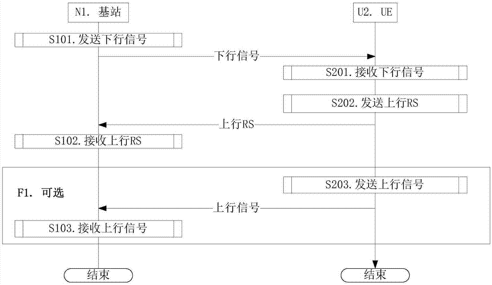
[0145] Embodiment 1 illustrates the flow chart of uplink transmission, as attached figure 1 shown. attached figure 1 In , base station N1 is the maintenance base station of the serving cell of UE U2, and the steps identified in block F1 are optional.

[0146] The base station N1 sends a downlink signal in step S101, receives an uplink RS in step S102, and receives an uplink signal in step S103.

[0147] UE U2 receives a downlink signal in step S201, sends an uplink RS in step S202, and sends an uplink signal in step S203.

[0148] In Embodiment 1, the bandwidth occupied by the downlink signal in a time window is less than or equal to 180 kHz, and the downlink signal indicates the first target position. The downlink signal includes at least one of {characteristic sequence, high-layer signaling, physical layer signaling}. The bandwidth occupied by the uplink RS in one time window is less than or equal to 180 kHz, the uplink RS occupies T time windows in the time domain, and ...

Embodiment 2

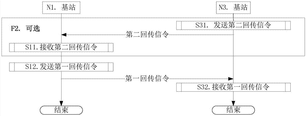
[0155] Embodiment 2 exemplifies the flow chart of cooperation between base stations to avoid inter-cell interference, as shown in the attached figure 2 shown. attached figure 2 , the steps identified in box F2 are optional steps.

[0156]The base station N1 receives the second backhaul signaling in step S11, and sends the first backhaul signaling in step S12.

[0157] The base station N3 sends the second backhaul signaling in step S31, and receives the first backhaul signaling in step S32.

[0158] In Embodiment 2, the first return signaling indicates the first target location in the present invention, and the second return signaling indicates the third target location. The third target position is the equivalent of the first target position in a given cell, that is, it indicates that the time-frequency resource occupied by the uplink RS in the given cell is within the {time domain position, frequency domain position} within the time window At least for time domain locat...

Embodiment 3

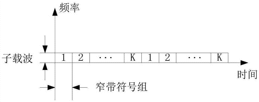
[0162] Embodiment 3 illustrates a schematic diagram of K candidate positions of uplink RSs in ST transmission, as shown in the attached image 3 shown.

[0163] attached image 3 In , a square filled with a number or a letter K represents Q resource units of a narrowband symbol group on a subcarrier.

[0164] In Embodiment 3, for ST transmission, the downlink signal in the present invention indicates the first target position from K candidate positions, and the first target position is the time-domain position of the time-frequency resource occupied by the uplink RS in the time window .

[0165] As a sub-embodiment 1 of Embodiment 3, the uplink RS occupies one narrowband symbol group within the time window, that is, the M in the present invention is 1. attached image 3 The resource units represented by the squares with the same number in , belong to two time windows respectively.

[0166] As a sub-embodiment 2 of Embodiment 3, the uplink RS occupies 2 narrowband symbol g...


PUM


Abstract

The invention discloses a method and device in narrowband wireless transmission. In one embodiment, UE receives a downgoing signal firstly, and the bandwidth occupied by the downgoing signal in a time window is smaller than or equal to 180 kHz; and then the UE sends an upgoing RS, and the bandwidth occupied by the upgoing RS in a time window is smaller than or equal to 180 kHz. The downgoing sign indicates a first target position, and the first target position comprises the time domain position of the time frequency resource occupied by the upgoing RS in the time window. The downgoing signal comprises a high-level signal. The upgoing RS occupies T time windows in the time domain, and occupies M narrowband symbol sets in the time windows, each narrowband symbol set includes Q narrowband symbols, and the upgoing RS occupies L1 subcarriers on each narrowband symbol in the M narrowband symbol sets. According to the invention, interference among cells is reduced, the channel estimation performance is improved, and redundancy of the upgoing RS is reduced.

Description

technical field [0001] The invention relates to a transmission scheme in a wireless communication system, in particular to a method and device for cellular network communication compatible with narrowband transmission. Background technique [0002] At the 3GPP (3rd Generation Partner Project, third-generation partnership project) RAN (Radio Access Network, wireless access network) #69 plenary meeting, NB-IOT (NarrowBand Internet of Things, narrowband Internet of Things) was established. NB-IOT supports 3 different operation modes (RP-151621): [0003] 1. Stand-alone operation, deployed on the frequency spectrum used by the GERAN system. [0004] 2. Guard band operation, deployed on unused resource blocks in the guard band of the LTE carrier [0005] 3. In-band operation, deployed on resource blocks on LTE (Long Term Evolution, long-term evolution) carriers [0006] Further, in NB-IOT, UE (User Equipment, user equipment) supports 180kHz RF (Radio Frequency, radio frequency...

Claims


Application Information

Patent Timeline
Patent Type & Authority Applications(China)
IPC IPC(8): H04L5/00H04W72/04H04W72/12
CPCH04L5/0053H04W72/1273H04W72/23
Inventor 张晓博
Owner SHANGHAI LANGBO COMM TECH CO LTD
Why Eureka
Try Eureka