
Fully-automatic FOG bonding machine Teflon plate clamping mechanism

A clamping mechanism and binding machine technology, applied in optics, instruments, electrical components, etc., to save adjustment time, ensure continuity, and improve efficiency

Active Publication Date: 2017-06-20
DALIAN YISHENGDA INTELLIGENT TECH
View PDF4 Cites 2 Cited by
  • Summary
  • Abstract
  • Description
  • Claims
  • Application Information

AI Technical Summary

Problems solved by technology

[0004] The invention aims to solve the clamping problem of the Teflon material tray in the FOG binding machine, and provides a fully automatic FOG binding machine Teflon material tray clamping mechanism

Method used


Image

  • Fully-automatic FOG bonding machine Teflon plate clamping mechanism
  • Fully-automatic FOG bonding machine Teflon plate clamping mechanism
  • Fully-automatic FOG bonding machine Teflon plate clamping mechanism

Examples


Embodiment Construction

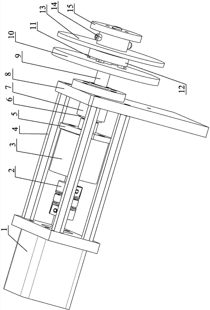
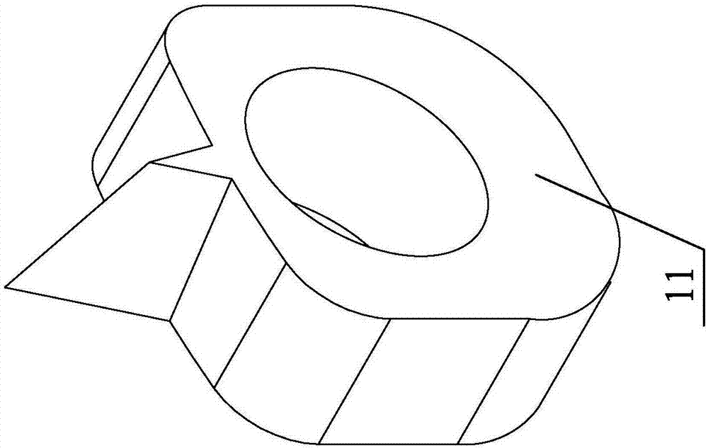
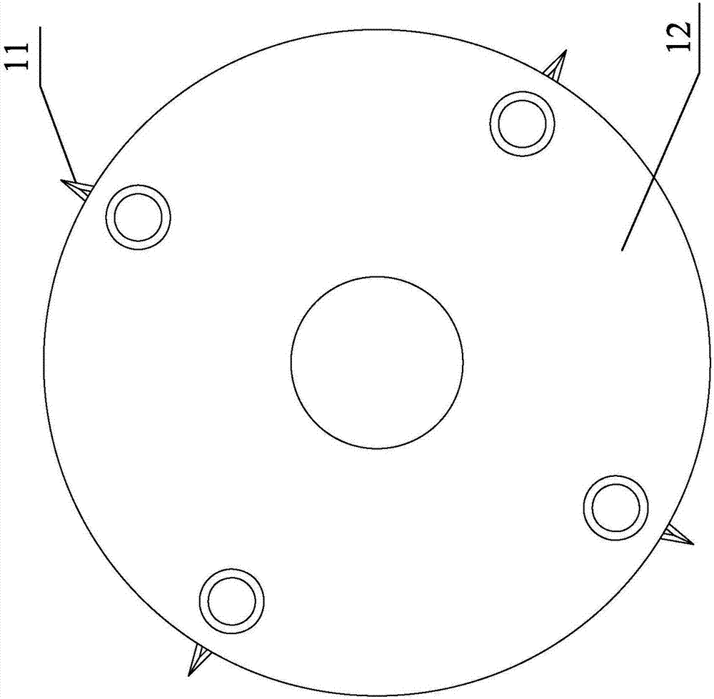
[0013] The invention discloses a Teflon material tray clamping mechanism for a fully automatic FOG binding machine. The structural components include a motor 1, a shaft coupling 2, a damper 3, a hexagonal column 4, a damper mounting plate 5, a bearing 6, and a bearing Mounting part 7, support plate 8, rotating shaft 9, rear material tray baffle plate 10, clamping material tray part 11, material tray guide 12, front material tray baffle plate 13, ball plunger 14, hand clasp 15.

[0014] Such as figure 1 As shown, the motor 1 drives the coupling 2, and transmits the rotation to the front damper mounting plate 5 through the damper 3, and the damper mounting plate 5 transmits the rotation to the rotating shaft 9 through the top screw, passing through the bearing 6 and the bearing mounting part 7 And the support of the support plate 8 enables the whole mechanism to be installed in a suitable position so that the overall structure can operate normally. Install the rear tray baffle ...


PUM


Abstract

The invention discloses a fully-automatic FOG bonding machine Teflon plate clamping mechanism. The fully-automatic FOG bonding machine Teflon plate clamping mechanism comprises a rotation shaft (9) which is driven to rotate by a motor (1); the front end of the rotation shaft (9) is sequentially sleeved with a disc-type rear plate baffle (10), a plate guiding piece (12) and a front plate baffle (13); four plate clamping pieces (11) are fixed circumferentially at equal angular distance intervals between the rear plate baffle (10) and the plate guiding piece (12) through bolts; each plate clamping piece (11) comprises a rotating body and an inclined triangular prism structural body extending outwardly from one side wall of the rotating body; and the outer end of the front plate baffle (13) is positioned and clamped through a ball head plunger (14) arranged in the rotation shaft (9) in a penetrating mode. According to the Teflon plate clamping mechanism provided by the invention, the labor-consuming and time-consuming working state for replacement of the original plate can be solved, the adjustment time is saved, operation continuity is ensured, and the efficiency is improved.

Description

technical field [0001] The invention relates to a mechanism in a full-automatic FOG binding machine, and more specifically relates to a Teflon material tray clamping mechanism. Background technique [0002] With the development of technology, rough and cumbersome working methods are gradually replaced by precise and fast working methods, and the degree of machine automation is getting higher and higher. With the development of this trend, the requirements for the working efficiency, continuity and precision of the machine are getting higher and higher. The accuracy of the mechanism restricts the processing quality of the product. Whether the mechanism is convenient and adjustable affects the continuity of the overall machine work and regular production capacity. The continuous supply and replacement of Teflon trays in the FOG binding machine will give Production brings good news. [0003] The problem is that the Teflon material tray of the FOG binding machine in the prior ...

Claims


Application Information

Patent Timeline
Patent Type & Authority Applications(China)
IPC IPC(8): H05K13/02G02F1/13
Inventor 李忠奎邹艳秋
Owner DALIAN YISHENGDA INTELLIGENT TECH
Learn More