Liquid level detection circuit, power supply control circuit and disinfectant manufacturing machine
A technology of power control circuit and liquid level detection, which is applied in the direction of liquid level indicators for physical variable measurement, and can solve problems such as the working status of disinfectant manufacturing machines
- Summary
- Abstract
- Description
- Claims
- Application Information
AI Technical Summary
Problems solved by technology
Method used
Image
Examples
Embodiment 1
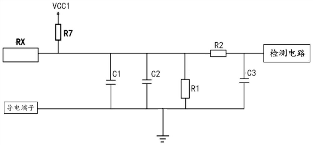
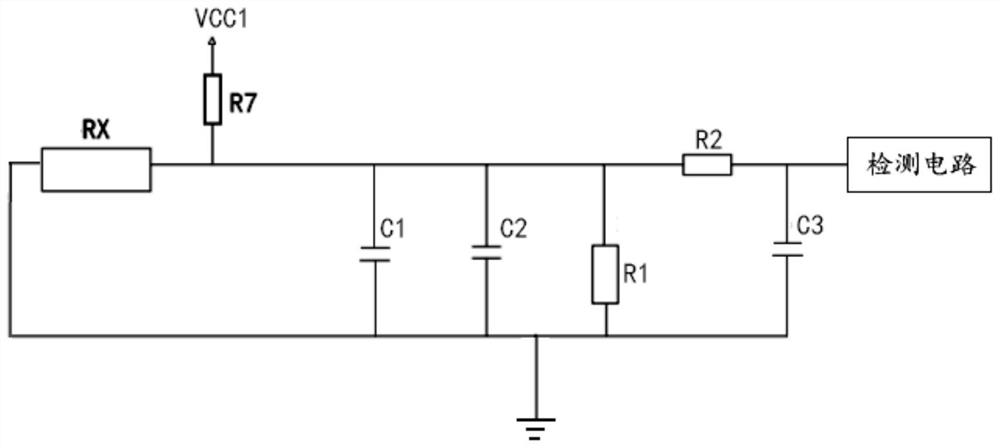
[0042] like figure 1 and figure 2 As shown, the embodiment of the present invention provides a liquid level detection circuit, and the liquid level detection circuit includes: a first power supply, a sampling circuit and a detection circuit.
[0043] The sampling circuit includes a plurality of sampling resistor groups serially connected in series, one end of the sampling circuit is connected to the first power supply through a voltage dividing resistor R7, and the other end is grounded. The detection circuit is connected between the voltage dividing resistor R7 and the sampling circuit, and the detection circuit is used to detect the voltage or current of the sampling circuit. In the embodiment of the present invention, the voltage detected by the detection circuit is used as an example for illustration. The sampling resistor group can be a single resistor, or multiple resistor groups connected in series and parallel.
[0044] In practical applications, multiple sampling ...
Embodiment 2
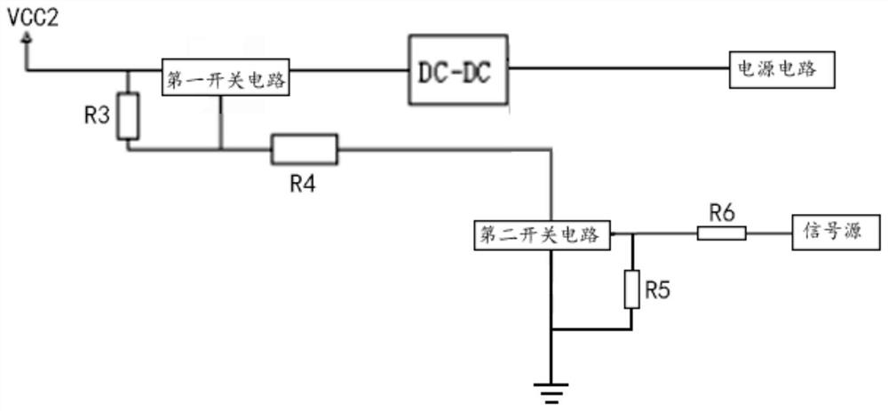
[0055] like image 3 and Figure 4 As shown, the embodiment of the present invention also provides a power control circuit, the power control circuit includes: a second power supply and a first switch circuit.
[0056] The control end of the first switch circuit is connected to the signal source, the first end is connected to the second power supply, and the second end is connected to the power circuit, which is used to supply power to the electrolysis device of the disinfectant solution maker.
[0057] The first switch circuit may be a switch tube, such as a triode, a MOS tube and other switching elements. like Figure 4 As shown, in this embodiment, the first switch circuit is a PMOS transistor U1. This embodiment only exemplifies the type of the first switch circuit and does not limit it. Those skilled in the art can change the type of the first switch circuit according to the actual situation, as long as the same technical effect can be achieved.
[0058] In this way, ...
Embodiment 3
[0065] like Figure 5 and Image 6 As shown, the embodiment of the present invention also provides a disinfectant production machine, which comprises: a control circuit; the liquid level detection circuit as described in any one, the liquid level detection circuit is electrically connected to the control circuit connection; the power control circuit according to any one, the power control circuit is electrically connected to the control circuit; the electrolysis device is connected to the power circuit in the power control circuit. The electrolysis device is used to electrolyze the electrolyte in the liquid storage container to generate disinfectant water.
[0066] Of course, in this embodiment, a control chip MCU may also be provided, and the control circuit, liquid level detection circuit, power control circuit and signal source are all provided in the control chip MCU. like Image 6 As shown, the sampling resistor group is placed vertically along the height direction of ...
PUM
 Abstract
Description
Claims
Application Information
 - R&D
- Intellectual Property
- Life Sciences
- Materials
- Tech Scout
- Unparalleled Data Quality
- Higher Quality Content
- 60% Fewer Hallucinations
Browse by: Latest US Patents, China's latest patents, Technical Efficacy Thesaurus, Application Domain, Technology Topic, Popular Technical Reports.
© 2025 PatSnap. All rights reserved.Legal|Privacy policy|Modern Slavery Act Transparency Statement|Sitemap|About US| Contact US: help@patsnap.com


