Textile machine

A technology for textile machines and workstations, which is applied in the direction of textiles, looms, and spinning machines. It can solve problems such as stoppage, insufficient monitoring of power supply units, and production stoppage of textile machines, so as to reduce energy consumption, prevent complete stoppage of production, and reduce The effect of small energy consumption

Pending Publication Date: 2022-02-22
SAURER SPINNING SOLUTIONS GMBH & CO KG
View PDF16 Cites 0 Cited by
  • Summary
  • Abstract
  • Description
  • Claims
  • Application Information

AI Technical Summary

Problems solved by technology

[0004] However, known textile machines of the type mentioned in the introduction have the disadvantage that the power supply units for supplying these stations are only insufficiently monitored, so that in the event of a failure of one or more power sources a complete stoppage of the textile machine and subsequent production stop

Method used


Image

  • Textile machine
  • Textile machine

Examples


Embodiment Construction

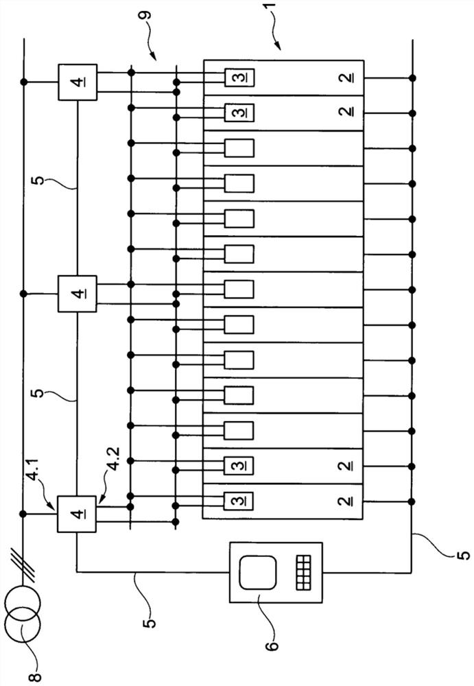
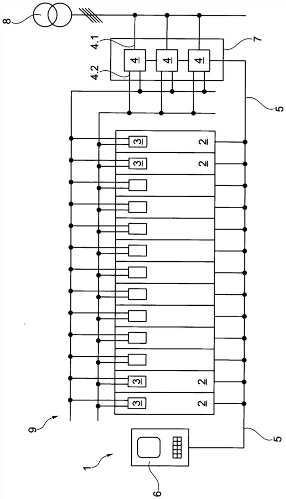
[0034] figure 1 A schematic diagram of the textile machine 1 of the present invention is shown. The textile machine 1 comprises a large number of work stations 2 arranged side by side. The station 2 can be designed, for example, as a winding position in a manner known per se. figure 1 As an example, only one power consumer 3 is shown per workstation 2 . The power consumer 3 is preferably designed as an electric drive. The textile machine 1 is provided with a Direct-voltage bar 9 along the length of the machine. The consumer 3 and possibly other not shown consumers of the workstation 2 are connected to a DC voltage rail for supplying electrical energy.

[0035] Distributed over the length of the textile machine 1 , a plurality, in this embodiment three, of power sources 4 are arranged, which together form a power supply unit of the textile machine 1 . In the exemplary embodiment shown, the power supply 4 is designed as a rectifier with a downstream DC voltage intermediate ...


PUM


Abstract

The invention relates to a textile machine, comprising a plurality of stations having at least one consumer, in particular an electric drive, and a power supply unit having a plurality of power sources for supplying the at least one consumer with electrical energy. The power sources are designed in such a way that each power source supplies electrical energy independently of one another to at least some of the stations and is connected in parallel on the output side in order to jointly supply the power consumer. In order to provide a textile machine with high fail-safe performance, it is provided that the power sources are designed to detect and transmit the power data and / or operating temperature thereof to the control unit.

Description

technical field [0001] The invention relates to a textile machine having a plurality of workstations with at least one power consumer, in particular an electric drive, and a power supply unit with a plurality of power sources for supplying electrical energy to at least one power consumer, wherein the power sources are designed in such a way that That is, each power supply supplies power to at least a part of the workstations independently of each other and is connected in parallel at the output side in order to jointly supply the power-consuming users. Background technique [0002] Many designs of textile machines of the type mentioned in the introduction are known from the prior art. Thus, DE 10 2015 014 177 A1 already shows a textile machine with a number of parallel stations, each station having a plurality of consumers of electricity, such as electric drives for winding shafts, yarn traversing devices and sensors. [0003] In order to supply power to the power-consuming...

Claims


Application Information

Patent Timeline
IPC IPC(8): D01H13/14D03D51/18D04B35/18H02M1/00H02M5/42
CPCD01H13/14D03D51/18D04B35/18H02M1/00H02M5/42D01H13/00H02M1/327H02M7/08H02M7/23D01H4/00B65H2701/31B65H63/04
Inventor 汉斯-冈特·威德肖温贝恩德-吕迪格·特尔G·布斯
Owner SAURER SPINNING SOLUTIONS GMBH & CO KG
Why Eureka
Try Eureka