Rotating adjusting type upper shaft mechanism for single-side polishing of large-size wafers
What is Al technical title?
Al technical title is built by PatSnap Al team. It summarizes the technical point description of the patent document.
A single-side polishing and rotation adjustment technology, applied in surface polishing machine tools, grinding/polishing equipment, grinding/polishing safety devices, etc., can solve uneven wafer grinding, poor wafer surface flatness, uneven distribution and other problems, to achieve the effect of improving polishing uniformity, improving sealing and improving flatness
Active Publication Date: 2017-06-23
TUNGHSU GRP
View PDF7 Cites 2 Cited by
Summary
Abstract
Description
Claims
Application Information
AI Technical Summary
This helps you quickly interpret patents by identifying the three key elements:
Problems solved by technology
Method used
Benefits of technology
Problems solved by technology
[0003] However, in the single-side polishing of large-sized and different-sized wafers, it is facing huge challenges and tests; the efficiency of polishing determines the cost of processing, and the uniformity of polishing and grinding determines the quality of processing; reducing costs and improving quality also Become the goal and direction of technology research and development
[0004] In the traditional single-sided polishing, the polishing method of ceramic disc patch stuck into the upper disc surface and the polishing process combining chemical and mechanical; due to the heat conduction effect, the temperature of the ceramic disc and the upper disc surface will increase with the increase of the polishing temperature. The principle of thermal expansion will lead to changes in the flatness of the surface of the ceramic disc and the upper disc surface; and the pressure of the upper axis acting on the single polished wafer will be unevenly distributed due to the change of the upper axis and the ceramic disc surface, resulting in wafer Uneven grinding, poor flatness of wafer surface after polishing
Method used
Image
Click on the blue label to locate the original text in one second.
Reading with bidirectional positioning of images and text.
Examples
Embodiment Construction
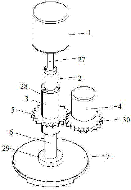
[0023] As shown in the figure, a rotary adjustable upper shaft mechanism for single-sided polishing of large-sized wafers, including a cylinder 1, a rotary joint 2, a rotary shaft 3, a rotary motor 4, a rotary gear 5, a connecting shaft 6 and an upper plate surface 7. It is characterized in that the cylinder 1 is fixed vertically, and its telescopic end is vertically downward, and the cylinder 1, the rotary joint 2, the rotary shaft 3, the connecting shaft 6 and the upper disk surface 7 are sequentially connected from top to bottom ;
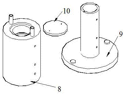
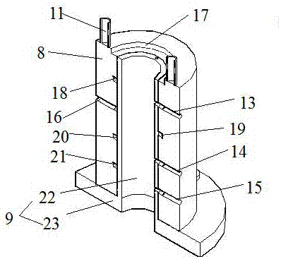
[0024] The rotary joint 2 is composed of an adapter sleeve 8, a rotating block 9 and a cover plate 10. The adapter sleeve 8 is in the shape of a hollow cylinder, on which a connecting rod 11, a sealed channel 12, an air pipe inlet 13, and a water pipe connection are arranged. Inlet 14, water pipe connection outlet 15 and water leakage detection port 16, the connecting rod 11 is vertically arranged on the upper end surface of the adapter sleeve 8...
PUM
Abstract
The invention provides a rotating adjusting type upper shaft mechanism for single-side polishing of large-size wafers. The rotating adjusting type upper shaft mechanism comprises a cylinder, a rotating connector, a rotating shaft, a rotating motor, a rotating gear, a connecting shaft rod and an upper disc face, wherein the cylinder controls the upper disc face to rise and fall, the rotating motor controls the rotating gear, the rotating shaft, a rotating block, the connecting shaft rod and the upper disc face to rotate, an air tube inlet port is connected with a pneumatic electronic valve, and a water tube inlet port and a water tube outlet port are connected with a water tank. The rotating adjusting type upper shaft mechanism for single-side polishing of the large-size wafers is simple in structure and reasonable in design, a rubber sealing piece and a water leakage detection port are arranged, the sealing performance of the rotating connector is effectively improved, and monitoring is provided for monitoring water leakage situation of the rotating connector; meanwhile, in the polishing operation process, the upper disc face can be effectively cooled, the situation that due to the fact that temperature of the upper disc face rises, flatness of a ceramic disc and the surface of the upper disc face is changed, and the stability is destroyed is avoided, and then polishing uniformity is improved, and the flatness of the surfaces of the polished wafers is improved; and a vacuum layer between the ceramic disc and the bottom of the upper disc face is easy to remove, and wafers can be taken out more rapidly.
Description
technical field [0001] The invention relates to the field of photovoltaics, in particular to a rotary adjustment type upper shaft mechanism for single-side polishing of large-sized wafers. Background technique [0002] With the continuous advancement of technology, the size of wafers is getting bigger and bigger, and the specifications of wafers are ever-changing; the requirements for processing quality are becoming more and more stringent. [0003] However, in the single-side polishing of large-sized and different-sized wafers, it is facing huge challenges and tests; the efficiency of polishing determines the cost of processing, and the uniformity of polishing and grinding determines the quality of processing; reducing costs and improving quality also Become the goal and direction of technology research and development. [0004] In the traditional single-sided polishing, the polishing method of ceramic disc patch stuck into the upper disc surface and the polishing process ...
Claims
Application Information
Patent Timeline
Application Date:The date an application was filed.
Publication Date:The date a patent or application was officially published.
First Publication Date:The earliest publication date of a patent with the same application number.
Issue Date:Publication date of the patent grant document.
PCT Entry Date:The Entry date of PCT National Phase.
Estimated Expiry Date:The statutory expiry date of a patent right according to the Patent Law, and it is the longest term of protection that the patent right can achieve without the termination of the patent right due to other reasons(Term extension factor has been taken into account ).
Invalid Date:Actual expiry date is based on effective date or publication date of legal transaction data of invalid patent.