Error calibration method based on genetic algorithm for six-degree-of-freedom series robot

A genetic algorithm and error calibration technology, which is applied to manipulators, genetic models, program-controlled manipulators, etc., can solve the problems of increased measurement difficulty and time for the accuracy of data sets, large error parameters, etc., to achieve simplicity and strong applicability , good versatility

Active Publication Date: 2017-06-23
HARBIN INST OF TECH
View PDF4 Cites 14 Cited by
  • Summary
  • Abstract
  • Description
  • Claims
  • Application Information

AI Technical Summary

Problems solved by technology

[0007] The purpose of the present invention is to solve the problem that the error parameters obtained by processing multiple data in the prior art have certain limitations and introduce some data with large errors,

Method used


Image

  • Error calibration method based on genetic algorithm for six-degree-of-freedom series robot
  • Error calibration method based on genetic algorithm for six-degree-of-freedom series robot
  • Error calibration method based on genetic algorithm for six-degree-of-freedom series robot

Examples


specific Embodiment approach 1

[0050] Specific implementation mode one: combine Figure 1 to Figure 3 and Figure 6 , Figure 7 The error calibration method for a six-degree-of-freedom serial robot based on a genetic algorithm in this embodiment is specifically prepared according to the following steps:

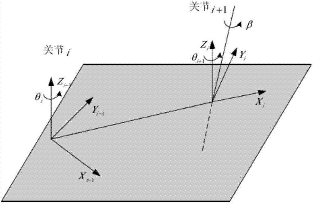
[0051] Step 1, establish the D-H error model of the robot, and introduce the parallel error angle β to establish the actual model of the robot;

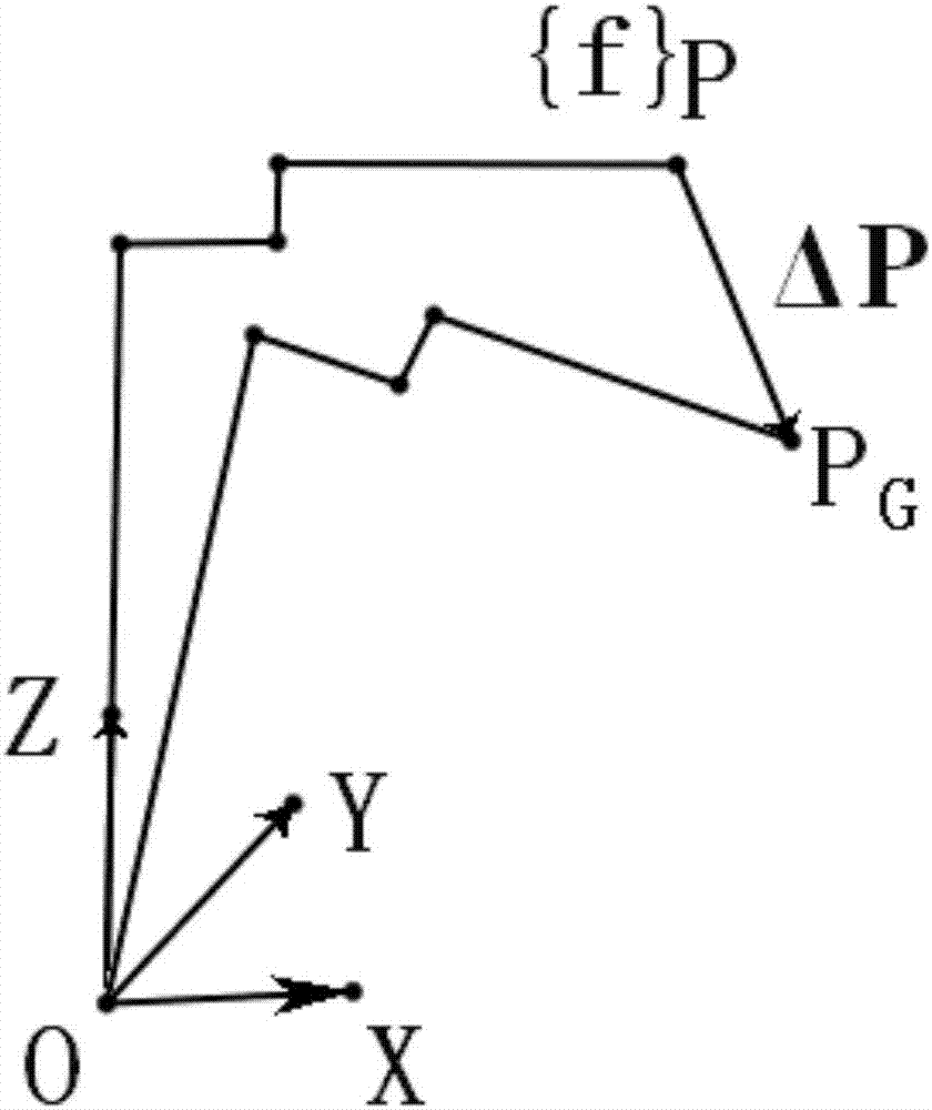
[0052] Step 2. Calculate the actual position P of the tool center of the robot according to the actual model of the robot G , according to P G and the theoretical position point P at the end of the robot arm (P G Theoretical position P) Calculate the robot error model of the robot, that is, the deviation △P:

[0053] ΔP=M θ △θ+M α △α+M a △a+M d △d+M β Δβ;

[0054] Among them, M θ is the joint angle coefficient matrix; M α is the torsion coefficient matrix; M a is the joint offset coefficient matrix; M d is the connecting rod offset coefficient matr...

specific Embodiment approach 2

[0086] Specific embodiment two: the difference between this embodiment and specific embodiment one is that the D-H error model of the robot is established in step one, and the actual model of the robot is established by introducing the parallel error angle β, which is specifically:

[0087] Step 11. Establish the D-H error model of the robot, specifying that the axes of the two connected connecting rods are respectively i and i-1; the common normal of the connecting rod axes i and i-1 is set as the length of the connecting rod a i-1 , the angle formed by the two connecting rods is set as the torsion angle αi-1 ; When the two axes i and i-1 are parallel, α i-1 =0; two common normals a i-1 and a i link offset d i , a i-1 and a i The angle between is set as the joint angle θ i ; among them, α i-1 The direction of is defined as the direction from the axis i-1 around the common perpendicular to i;

[0088] Step 12: In the robot D-H error model, add the parallel error angle β...

specific Embodiment approach 3

[0092] Specific embodiment three: the difference between this embodiment and specific embodiment one or two is: in step two, calculate the actual position P of the robot tool center according to the actual model of the robot G , according to P G and the theoretical position point P at the end of the robot arm (P G The theoretical position P) calculates the robot error model of the robot, that is, the deviation △P is specifically:

[0093] Step 21. Calculate the actual position P of the tool center of the robot according to the actual model of the robot G , the P G and the theoretical position point P at the end of the robot arm (P G Theoretical position P) represents the deviation △P of the robot:

[0094] P G =P+△P

[0095] Among them, P G is the actual position of the end of the robot arm relative to the robot base coordinate system {O}, which is directly obtained by the laser calibration instrument, {O} is the base coordinate system where the robot is located, point ...


PUM


Abstract

The invention provides an error calibration method based on a genetic algorithm for a six-degree-of-freedom series robot, and relates to the error calibration method for the robot. The error calibration method based on the genetic algorithm for the six-degree-of-freedom series robot aims to solve the problems that in the prior art, multidata cannot be processed, an obtained error parameter has a certain limitation, some data with great errors are introduced, and then the accuracy of a whole data set is influenced, and the measuring difficulty and time are increased. The method comprises the steps of 1, establishing a real model of the robot; 2, calculating a robot error model of the robot and obtaining a matrix; 3, establishing an error optimization model; 4, obtaining an error parameter X of the robot; 5, searching for an optimal error parameter of the robot; 6, feeding the obtained optimal error parameter back to the robot according to an error compensation strategy, and the like. The error calibration method based on the genetic algorithm for the six-degree-of-freedom series robot is applied to the field of the error calibration method for the robot.

Description

technical field [0001] The invention relates to an error calibration method for a six-degree-of-freedom serial robot, in particular to a genetic algorithm-based error calibration method for a six-freedom serial robot. Background technique [0002] Robot calibration technology is one of the important links in the high-precision work of robots. Robot calibration ensures that the robot can accurately complete the specified tasks. Robot calibration is based on kinematics. By establishing an error model, identifying error parameters, and proposing an error compensation strategy, the accuracy of the robot is improved. [0003] The so-called calibration is the process of identifying the accurate parameters of the robot model by using advanced measurement methods and model-based parameter identification methods, and compensating the robot error by using additional control algorithms or modifying the original control algorithm, thereby improving the absolute accuracy of the robot. ...

Claims


Application Information

Patent Timeline
IPC IPC(8): B25J9/16G05D1/02G06N3/12
Inventor 高会军林伟阳董文博李湛邱剑彬杨学博于兴虎
Owner HARBIN INST OF TECH
Why Eureka
Try Eureka