Rod pumped well real-time work condition diagnosing method based on time sequence surface dynamometer cards

A technology of real-time working conditions and diagnostic methods, which is used in construction and other directions

Active Publication Date: 2017-06-23
CHINA UNIV OF PETROLEUM (EAST CHINA)
View PDF5 Cites 14 Cited by
  • Summary
  • Abstract
  • Description
  • Claims
  • Application Information

AI Technical Summary

Problems solved by technology

The key to this method is the selection of standard dynamometer diagrams, and this selection process depends more on the experience of field engineers, so...

Method used


Image

  • Rod pumped well real-time work condition diagnosing method based on time sequence surface dynamometer cards
  • Rod pumped well real-time work condition diagnosing method based on time sequence surface dynamometer cards
  • Rod pumped well real-time work condition diagnosing method based on time sequence surface dynamometer cards

Examples


Embodiment 1

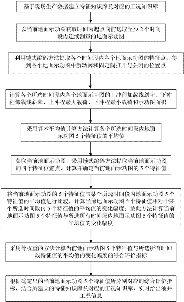
[0077] A method for diagnosing real-time working conditions of pumping wells based on time-series ground dynamometer diagrams, including: establishing a feature knowledge base and a corresponding working condition knowledge base based on on-site production data; Obtain the ground dynamometer diagram; use the chain coding method to extract the feature points of each ground dynamometer diagram in each time period, and obtain the opening and closing positions of the floating valve and the fixed valve in each ground dynamometer diagram; calculate each selected time period The eigenvalues ​​of each ground dynamometer diagram in the plot include: the slope of the upstroke loading line, the slope of the downstroke unloading line, the maximum load on the upstroke, the minimum load on the downstroke, and the area of ​​the dynamometer diagram; then, the current ground dynamometer is calculated using the method of equal weight The comprehensive evaluation index of the change range of the ...

Embodiment 2

[0079] As described in Example 1, a method for diagnosing real-time operating conditions of pumping wells based on time-series ground dynamometer diagrams, the difference is that the feature knowledge base includes the range of slope variation of the upstroke loading line of the ground dynamometer diagram, the downstroke The variation range of the slope of the stroke unloading line, the variation range of the maximum load of the upstroke, the variation range of the minimum load of the downstroke and the variation range of the area of ​​the dynamometer diagram;

[0080] The working condition knowledge base includes increasing the stroke frequency of the pumping unit, decreasing the stroke frequency of the pumping unit, increasing the stroke of the pumping unit, reducing the stroke of the pumping unit, increasing the back pressure, decreasing the back pressure, and changing the casing pressure. Large, small casing pressure, oil well pump fixed valve leakage, oil well pump floatin...

Embodiment 3

[0083] As described in Embodiment 1 and 2, a method for diagnosing real-time working conditions of pumping wells based on time-series ground dynamometer diagrams, the difference is that the chain coding method is used to extract the characteristics of each ground dynamometer diagram in each time period Points to get the opening and closing positions of the floating valve and the fixed valve in each ground dynamometer diagram;

[0084] The characteristic points of the ground dynamometer diagram describe the opening and closing position points of the floating valve and the fixed valve during the up and down stroke of the pumping unit;

[0085] The chain coding method includes: for each ground dynamometer diagram, the displacement d n and load l n The parameters are normalized, d min 、d max , l min , l max are the minimum and maximum values ​​of displacement and load, respectively; calculate any set of normalized displacements d dn and load l dn The vector angle A correspo...


PUM


Abstract

The invention discloses a rod pumped well real-time work condition diagnosing method based on time sequence surface dynamometer cards. The rod pumped well real-time work condition diagnosing method comprises the following steps: establishing a characteristic knowledge base and a corresponding work condition knowledge base based on site production data; continuously measuring the surface dynamometer cards in each time quantum before the current surface dynamometer card is selected; using a chained encoding method to extract characteristic points of each surface dynamometer card in each time quantum, and obtaining the turning-on and turning-off positions of traveling valves and fixed valves in each surface dynamometer card; calculating the characteristics values of each surface dynamometer card in each selected time quantum, including upstroke loaded line slope, down stroke unloaded line slope, upstroke maximum load, down stroke minimum load and dynamometer card area; then, adopting an equal weight method to calculate the comprehensive evaluation index of variation amplitude of the average value of the characteristic value of the current surface dynamometer card and the selected characteristic value of all time quantum; and finally giving out oil well work condition information in combination with the characteristic knowledge base and a corresponding work condition knowledge base according to the comprehensive evaluation index.

Description

technical field [0001] The invention relates to a method for diagnosing real-time working conditions of pumping wells based on time-series surface dynamometer diagrams, and belongs to the technical field of petroleum exploitation. Background technique [0002] The pumping well production system is the most widely used artificial lift method at present. The surface dynamometer diagram describing the change of the suspension point load of the pumping unit with the displacement of the suspension point is an important technology for analyzing and diagnosing the working conditions of the pumping well and improving the production management level of the pumping well. With the advancement of monitoring technology, real-time collection of surface dynamometer data of pumping wells has become a reality. The real-time analysis of the ground dynamometer data can provide real-time decision support for production management. [0003] Ding Tao and Liu Junrong disclosed in the Chinese pat...

Claims


Application Information

Patent Timeline
IPC IPC(8): E21B47/008
CPCE21B47/008
Inventor 刘均荣曹世杰李博宇
Owner CHINA UNIV OF PETROLEUM (EAST CHINA)
Why Eureka
Try Eureka