A film-sealed piezoelectric-driven micro-spray lubrication device

A piezoelectric-driven, spray-lubricated technology, applied in the direction of engine lubrication, engine components, bearing components, etc., can solve problems such as mechanical failure of spacecraft precision parts bearings, improve energy utilization, increase the scope of application, and increase pressure The effect of wave strength

Inactive Publication Date: 2018-09-07
HARBIN INST OF TECH
View PDF8 Cites 0 Cited by
  • Summary
  • Abstract
  • Description
  • Claims
  • Application Information

AI Technical Summary

Problems solved by technology

[0005] In order to solve the problem of mechanical failure of the existing spacecraft precision component bearings, the present invention further proposes a film-sealed piezoelectric-driven micro-spray lubrication device

Method used


Image

  • A film-sealed piezoelectric-driven micro-spray lubrication device
  • A film-sealed piezoelectric-driven micro-spray lubrication device
  • A film-sealed piezoelectric-driven micro-spray lubrication device

Examples


specific Embodiment approach 1

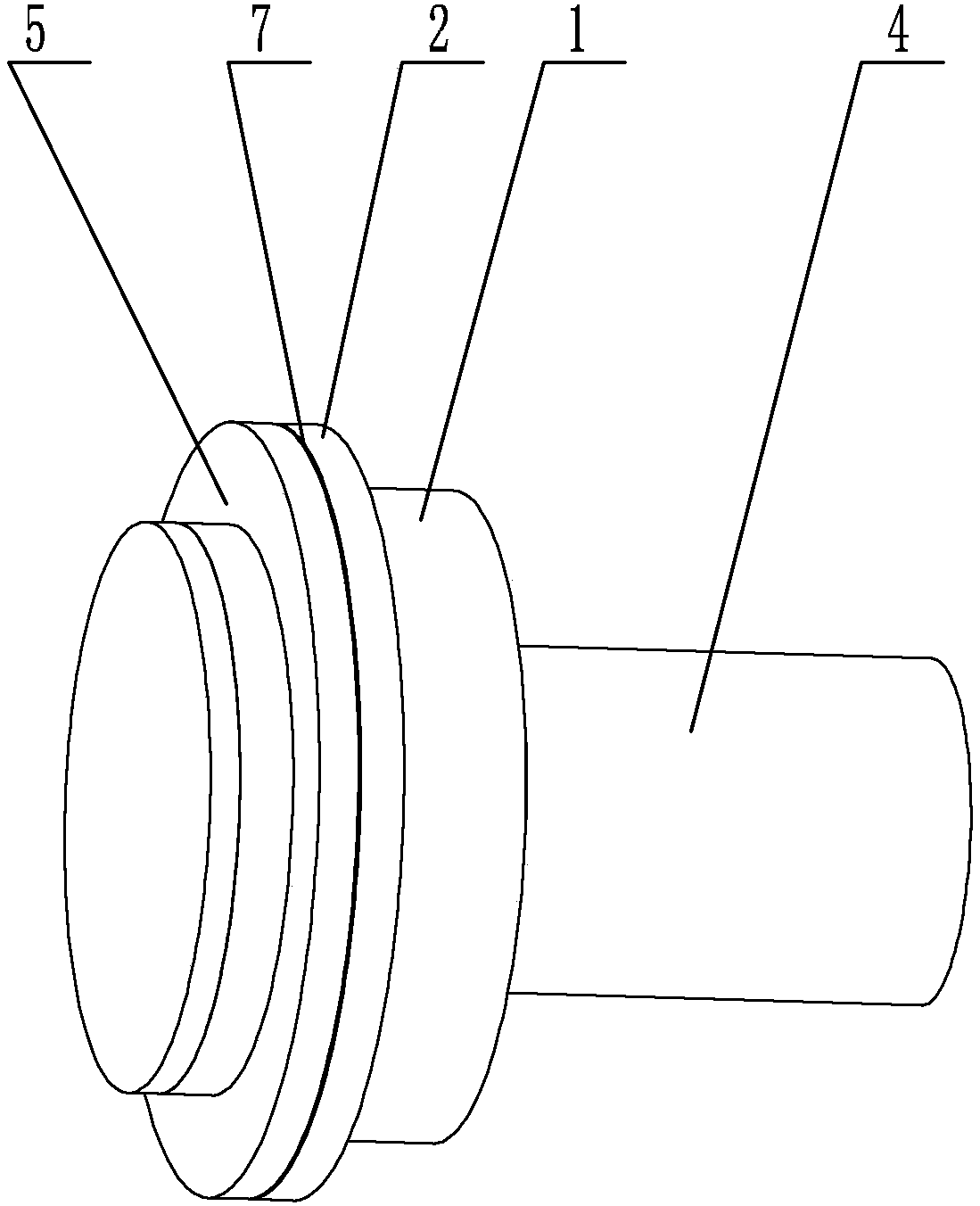
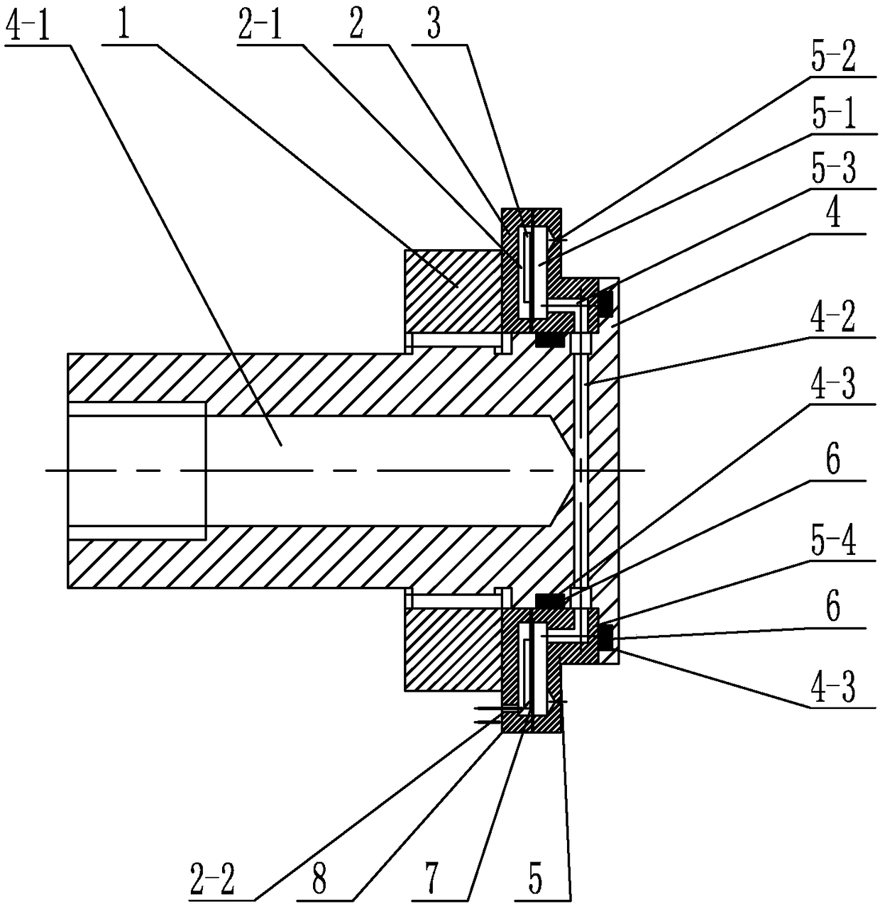
[0024] Specific implementation mode one: combine Figure 1 to Figure 10 Describe this embodiment, a film-sealed piezoelectric-driven micro-spray lubrication device described in this embodiment includes a lock nut 1, a micro-spray rear cover 2, an oil supply mandrel 4, a micro-spray front cover 5, and a piezoelectric vibrator , the middle part of the rear end of the oil supply mandrel 4 is provided with an oil supply chamber 4-1 along the axial direction, and the front end of the oil supply chamber 4-1 is symmetrically provided with a plurality of oil supply passages 4-2 along the radial direction, and the oil supply passage 4 -2 communicates with the oil supply chamber 4-1, the micro-spray rear cover 2 and the micro-spray front cover 5 are set on the outside of the oil supply mandrel 4, the micro-spray front cover 5 is fixedly connected to the oil supply mandrel 4, and after micro-spray Cover 2 is arranged on the rear end of micro-spray front cover 5, and the rear end of micro...

specific Embodiment approach 2

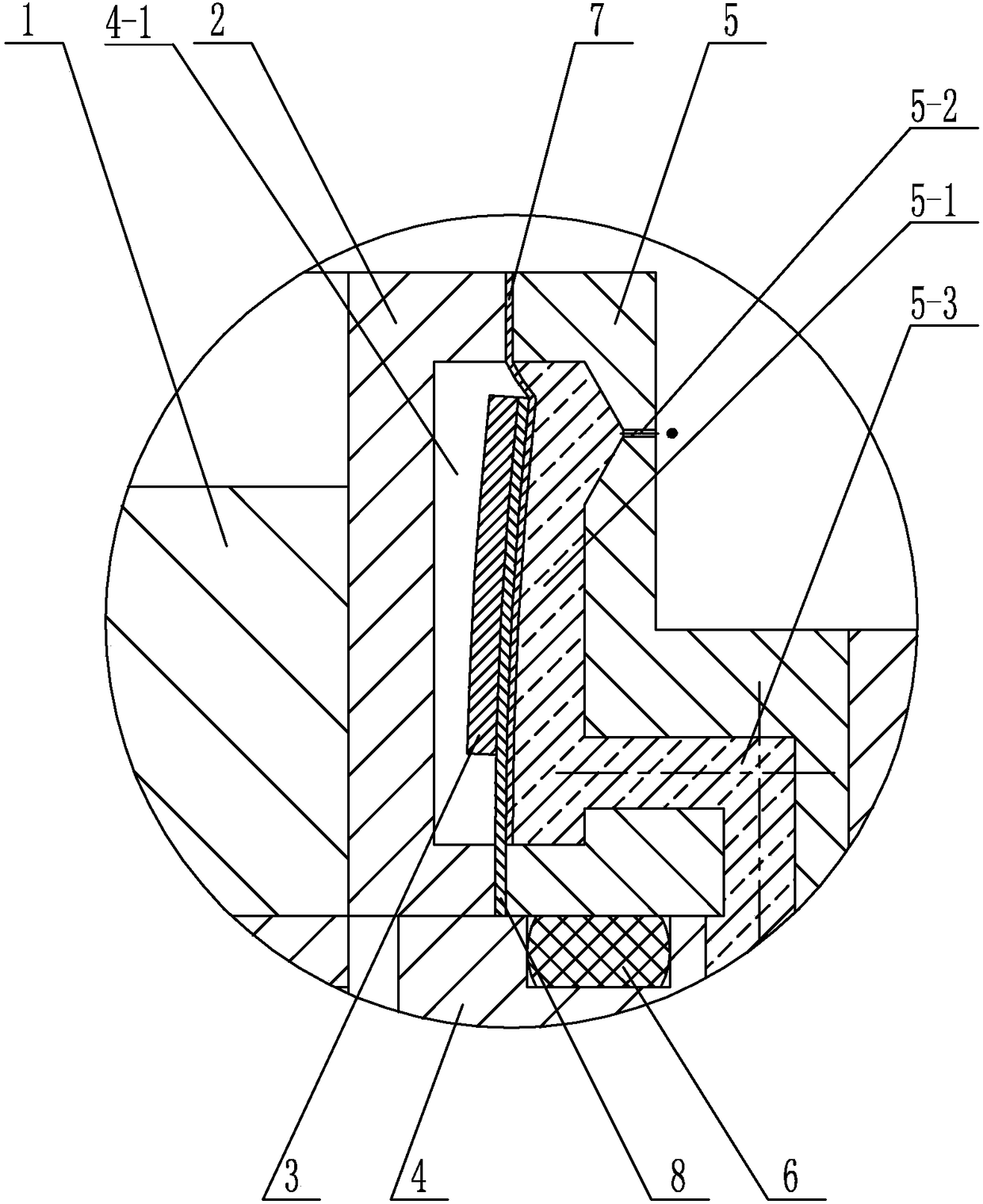
[0030] Specific implementation mode two: combination Figure 1 to Figure 5 Describe this embodiment, the elastic film 7 described in this embodiment is fixed on the front end surface of the copper sheet 8, the piezoelectric ceramic sheet 3 is fixed on the middle part of the rear end surface of the copper sheet 8, and the inner side of the copper sheet 8 is fixed on the front end surface of the copper sheet 8. The inner side between the cover 2 and the micro-spray front cover 5, the outer side of the copper sheet 8 is arranged in the annular groove 2-1, and the outer side of the elastic film 7 is fixed on the outer side between the micro-spray rear cover 2 and the micro-spray front cover 5 , The inner side of the elastic film 7 is set in the injection chamber 5-1. Other compositions and connection methods are the same as those in Embodiment 1.

[0031] In this embodiment, the elastic film 7 is fixed on the front end surface of the copper sheet 8 , the inner diameter of the cop...

specific Embodiment approach 3

[0033] Specific implementation mode three: combination figure 2 Describe this embodiment, the rear end surface of the micro-sprayed back cover 2 described in this embodiment is provided with through hole 2-2, and the positive electrode lead wire of driving power is connected with piezoelectric ceramic chip 3, and draws out from through hole 2-2, drives The negative electrode lead wire of the power supply is connected with the back cover 2 of micro-spraying. Other compositions and connection modes are the same as those in Embodiment 1 or 2.


PUM


Abstract

The invention discloses a thin film sealing type piezoelectric driving trace jet lubrication device and relates to the technical field of space lubrication and piezoelectric driven trace jet lubrication. According to the thin film sealing type piezoelectric driving trace jet lubrication device, the problem that bearing machinery of a precision part of an existing spacecraft loses efficacy is solved. The thin film sealing type piezoelectric driven trace jet lubrication device comprises a locking nut, a trace jet rear cover, an oil supply core shaft, a trace jet front cover and a piezoelectric vibrator. An oil supply cavity is formed in the middle of the rear end of the oil supply core shaft in the axial direction. A plurality of oil supply channels are symmetrically arranged at the front end of the oil supply cavity in the radial direction and communicate with the oil supply cavity. The trace jet rear cover is arranged at the rear end of the trace jet front cover. The piezoelectric vibrator is arranged between the trace jet rear cover and the trace jet front cover. A plurality of oil jetting openings are uniformly formed in the outer side of the front end face of the trace jet front cover in the circumferential direction. An oil jetting cavity communicates with the oil jetting openings. A plurality of oil jetting channels are uniformly formed inside the trace jet front cover in the circumferential direction. One ends of the oil jetting channels are connected with the oil jetting cavity, and the other ends of the oil jetting channels are connected with oil supply channels. The thin film sealing type piezoelectric driven trace jet lubrication device is used for piezoelectric driving trace jet lubrication.

Description

technical field [0001] The invention relates to the technical fields of space lubrication and piezoelectric micro-spray lubrication, in particular to a film-sealed piezoelectric-driven micro-spray lubrication device. Background technique [0002] The mechanical failure of the bearings in the precision parts inside the spacecraft is one of the important reasons for the operation failure of the entire spacecraft. Therefore, to ensure that the spacecraft can work stably for a long time, the problem of mechanical failure of the bearings inside the spacecraft must be solved first. The volatilization and deterioration of lubricating oil caused by the harsh working environment of spacecraft are the main reasons for the mechanical failure of bearings. Although solid lubricants are superior to liquid lubricants in stability, their use on precision parts is limited. Therefore, it is very important to improve the life of lubricating oil and design a stable oil supply device. [0003] ...

Claims


Application Information

Patent Timeline
Patent Type & Authority Patents(China)
IPC IPC(8): F16N7/00
CPCF16N7/00F16N2210/14F16N2270/70
Inventor 刘军考李锴杨锐陈维山
Owner HARBIN INST OF TECH
Why Eureka
Try Eureka