
Robot 3D repeated positioning precision test system

A repeat positioning accuracy and testing system technology, applied in the direction of instruments, measuring devices, optical devices, etc., can solve problems such as test speed drop, large positioning measurement error, and different surface accuracy cannot be guaranteed to be consistent, so as to improve stability and reduce The effect of overall weight

Inactive Publication Date: 2017-06-23
上海砺晟光电技术有限公司 +1
View PDF5 Cites 18 Cited by
  • Summary
  • Abstract
  • Description
  • Claims
  • Application Information

AI Technical Summary

Problems solved by technology

[0004] (1) The three sensors work relatively independently, and are respectively connected to data acquisition systems such as PLC or industrial computer, so the synchronization of sampling by the three sensors cannot be guaranteed
Moreover, the acquisition process generally involves communication with each sensor one by one. The actual time required to obtain a set of three-dimensional coordinates is three times the sampling period of a single sensor, which leads to a decrease in the test speed of the entire system and cannot meet the needs of rapid production;
[0005] (2) The positioning method of the sensor and the bracket and the bracket itself is not good. The three sensors cannot guarantee reliable and accurate orthogonal positioning accuracy (such as 2015100985690), or the three sensors cannot be flexibly adjusted (such as 2014101018958);
[0006] (3) The reflective surface of the laser displacement sensor directly adopts the surface at the end of the robot body, the measurement accuracy of the sensor cannot be guaranteed, and the accuracy of different surfaces cannot be guaranteed to be consistent;
[0007] (4) Various existing methods cannot guarantee that the intersection points of the measurement lines of the three laser displacement sensors are at the same point in space, which will result in a large positioning measurement error

Method used


Image

  • Robot 3D repeated positioning precision test system
  • Robot 3D repeated positioning precision test system
  • Robot 3D repeated positioning precision test system

Examples


Embodiment Construction

[0040] The embodiments of the present invention will be described in detail below in conjunction with the accompanying drawings. This embodiment is implemented on the premise of the technical solution of the present invention, and detailed implementation methods and specific operating procedures are provided, but the protection scope of the present invention is not limited to the following Example.

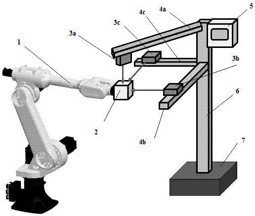
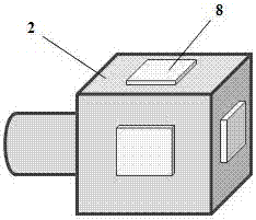
[0041] The present invention proposes a robot three-dimensional repetitive positioning accuracy test system based on a laser displacement sensor and a synchronous controller, such as figure 1 shown. The system includes: a reflector 2, a sensor 3, a bracket 4, a controller 5, a column 6, a base 7, etc., wherein: the sensor 3 has three 3a, 3b, 3c, which are respectively fixed on the three brackets 4a, Above 4b and 4c; the three sensors are arranged in pairs of 3a, 3b and 3c in orthogonal directions, and the three laser beams are projected to the reflector 1 at the same time.

[00...


PUM


Abstract

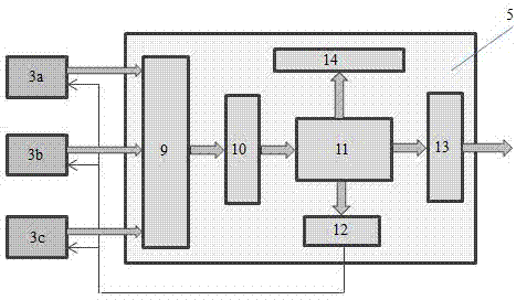
The present invention discloses a robot 3D repeated positioning precision test system. The system is characterized in that the system comprises a reflector, sensors, brackets, a controller, a vertical column, and a base, the reflector is rigidly connected to a robot end and moves and rotates with the robot end, three sensors are fixed to three brackets in a direction of pairwise orthogonal and three laser beams are projected to the reflector at the same time, the brackets are reliably fixed to the vertical column and are responsible for positioning and fixing the sensors, and the controller is arranged at one side of the vertical column. The sensors are laser displacement sensors with an external trigger function, the controller is formed by a collector, a cache, a processor, a trigger, a display device, and a communication interface, the synchronous acquisition of three-dimensional coordinates can be realized, and a synchronization error is avoided. At the same time, the invention discloses a calibrator and a corresponding sensor azimuth calibration method.

Description

technical field [0001] The invention relates to a robot three-dimensional repetitive positioning accuracy testing system, in particular to a robot three-dimensional repetitive positioning accuracy testing system based on a laser displacement sensor and a synchronous acquisition controller. Background technique [0002] The robot is an open-loop kinematic structure. The angle value of the joint rotation is obtained through the angle measuring device (usually an incremental code disc), and the spatial pose of the current robot end effector is obtained through the robot kinematics model. Due to the inevitable existence of various errors in the mechanical manufacturing and assembly, encoder, motion control and other links in the robot production process, the gravity deformation, thermal deformation, gap and wear and other random errors in the use of the robot, etc., the robot Compared with the ideal value, the actual spatial pose of the end usually has a large deviation, which a...

Claims


Application Information

Patent Timeline
IPC IPC(8): G01B11/00
CPCG01B11/002
Inventor 不公告发明人
Owner 上海砺晟光电技术有限公司
Learn More