Tank type erosion abrasion testing device and method

A wear test and erosion technology, applied in the direction of testing wear resistance, etc., can solve the problems affecting the use range of the tank type erosion wear test device, unfavorable research on the erosion wear performance of wear-resistant materials, and the limited range of angle adjustment. Avoid uneven slurry concentration, not easy to eddy current, and improve the effect of accuracy

Active Publication Date: 2017-06-23
中钢不锈钢管业科技山西有限公司
View PDF7 Cites 3 Cited by
  • Summary
  • Abstract
  • Description
  • Claims
  • Application Information

AI Technical Summary

Problems solved by technology

[0005] 2. The erosion angle is an important factor affecting the wear resistance of wear-resistant materials. At present, the adjustment and control of the erosion angle of the domestic tank-type erosion wear test device is mostly realized by changing different sample discs or fixtures. Not only It is inconvenient in actual use, and the angle adjustment range is very limited, which greatly affects the application range of the tank type erosion wear test device
[0006] 3. The non-uniform slurry concentration of the tank-type erosion wear device at low speed and high concentration is a disadvantage that cannot be ignored
[0007] 4. Most of the existing tank-type erosion and wear test devices are eroded by the mud body when the sample is rotating, and mostly fixed by wear-resistant materials when working, and are eroded by the flowing mud (for example: the bushing in the pump, Cyclone lining), the existing tank-type erosion wear test device can not be well simulated, which is not conducive to the study of the erosion wear performance of wear-resistant materials

Method used


Image

  • Tank type erosion abrasion testing device and method
  • Tank type erosion abrasion testing device and method
  • Tank type erosion abrasion testing device and method

Examples


Embodiment Construction

[0029] The following will clearly and completely describe the technical solutions in the embodiments of the present invention with reference to the accompanying drawings in the embodiments of the present invention. Obviously, the described embodiments are only some, not all, embodiments of the present invention. Based on the embodiments of the present invention, all other embodiments obtained by persons of ordinary skill in the art without making creative efforts belong to the protection scope of the present invention.

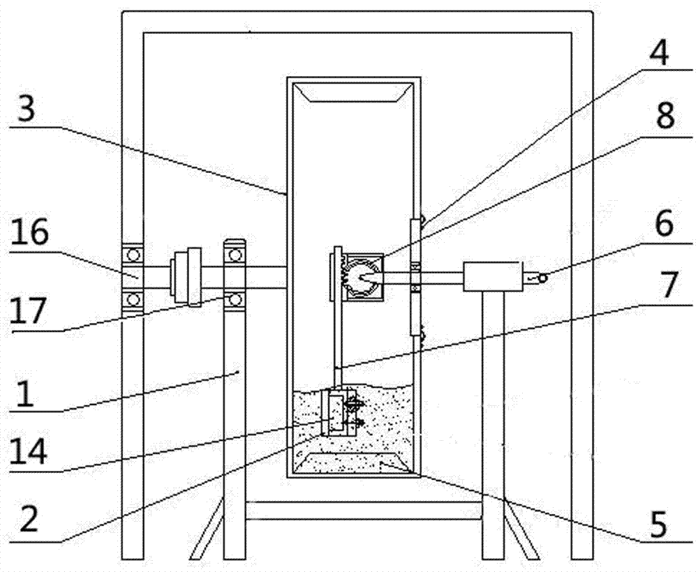
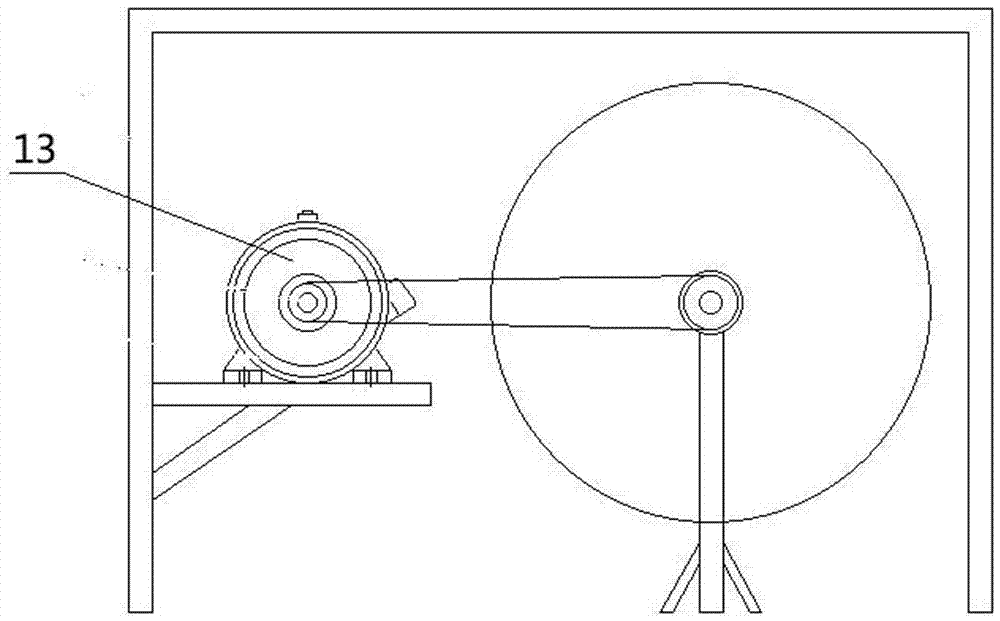
[0030] Such as Figure 1~2 Shown: a pot-type erosion wear test device, including a bracket 1 and a sample holder 2, the bracket 1 is provided with a rotatable hollow drum 3, and the sample holder 2 is arranged inside the hollow drum 3 and connected with the bracket 1 , The hollow cylinder 3 is provided with a sealing cover 4, the sample 14 on the sample holder 2 can be taken out by opening the sealing cover 4, and the inner wall of the hollow cylinder 3 is pro...


PUM


Abstract

The invention belongs to the technical field of wear test devices, and in particular relates to a tank type erosion wear test device and method. The tank type erosion wear test device comprises a bracket and a test sample clip, wherein the bracket is provided with a rotatable hollow roller; the hollow roller is provided with a sealing cover; a through hole is formed in the hollow roller or the sealing cover; the test sample clip is arranged in the hollow roller and is connected with the bracket; when the hollow roller rotates, the test sample clip is static and immobile; a blade is arranged on an inner wall of the hollow roller. According to the tank type erosion abrasion testing device and method, types of slurry milling materials, pH (Potential of Hydrogen) values of slurry, an erosion linear speed of a test sample and an erosion angle all can be adjusted, and the tank type erosion wear test device is applicable to researches on performance of wear-resisting materials; the position of the test sample in the hollow roller can be adjusted through a displacement device, and demands on the size of the test sample are not strict; tests for erosion wear performance of the test sample at different positions are realized; the adjustment of the erosion angle in a range of 0 to 90 degrees can be realized by adjusting the test sample clip.

Description

technical field [0001] The invention belongs to the technical field of wear test devices, and in particular relates to a tank type erosion wear test device and a method. Background technique [0002] The wear performance of materials is a topic of concern to researchers. On the one hand, wear is the main form of component failure, especially in metallurgy, mining, construction machinery, electric power, coal, petroleum and other fields; on the other hand, the economic loss caused by wear is also huge. More than 3 million tons, nearly 15 billion US dollars, of which abrasive wear accounts for more than 50%. Therefore, it is necessary to research and develop new erosion wear devices. [0003] There are many classification methods for erosion and wear test devices, and the common classification methods are jet type, vacuum drop type and tank type. Due to its simple structure and numerous advantages, the tank test device is mostly used for erosion and wear tests of wear-resis...

Claims


Application Information

Patent Timeline
IPC IPC(8): G01N3/56
CPCG01N3/56
Inventor 吴瑞瑞李秋书王荣峰王康康王孝国宁小丹
Owner 中钢不锈钢管业科技山西有限公司
Why Eureka
Try Eureka