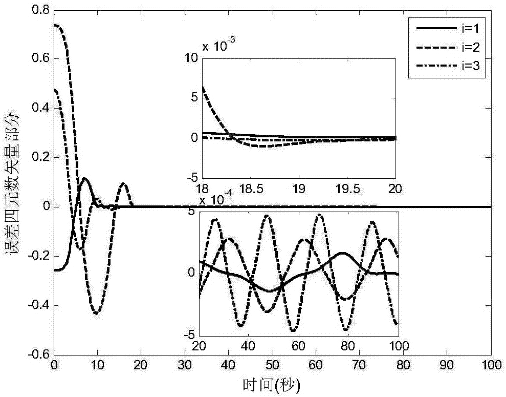
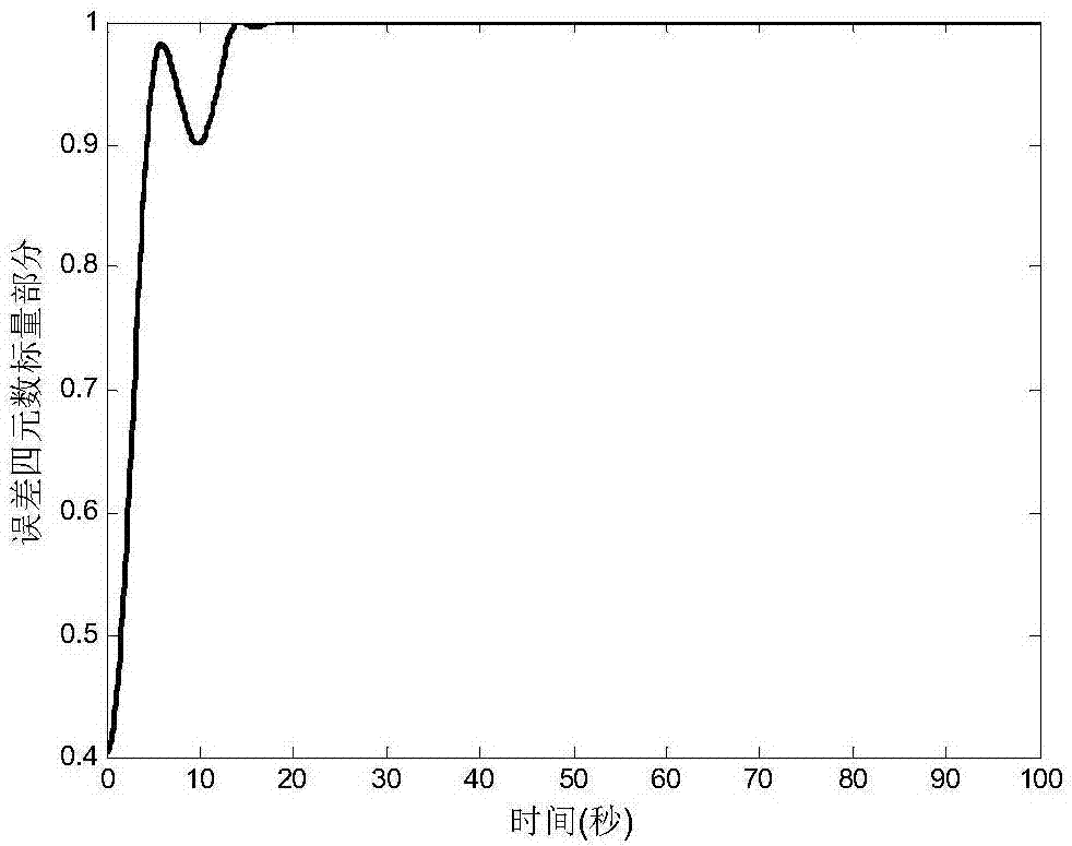
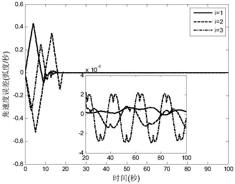
Spacecraft robust finite time saturation attitude tracking control method
A limited-time, tracking control technology, applied in adaptive control, general control system, control/regulation system, etc., can solve the problems of limited application scope of control algorithm, complex controller structure, uncertain model, etc., and achieve control parameters. The tuning process is simple, the convergence speed is accelerated, and the applicability is enhanced.
- Summary
- Abstract
- Description
- Claims
- Application Information
AI Technical Summary
Problems solved by technology
Method used
Image
Examples
specific Embodiment approach 1
[0038] Specific implementation mode one: a spacecraft robust finite-time saturation attitude tracking control method in this implementation mode includes the following steps:
[0039] Step 1: Establish the attitude kinematics and dynamics model of the rigid body spacecraft, that is, the attitude tracking system;
[0040] Step 2: Define fast non-singular terminal sliding surface and auxiliary system according to Step 1;
[0041] Step 3: Design a robust finite-time saturation attitude tracking controller;
[0042] When the upper bound of the integrated uncertainty δ of the attitude tracking system is an unknown constant, a robust finite-time saturated attitude tracking controller is designed according to the fast non-singular terminal sliding mode surface obtained in step 2 and the auxiliary system;
[0043] When the upper bound of the comprehensive uncertainty δ of the attitude tracking system is an unknown function, an adaptive robust finite-time saturated attitude tracking c...
specific Embodiment approach 2
[0044] Specific embodiment two: the difference between this embodiment and specific embodiment one is: the specific process of establishing the attitude kinematics and dynamics model of the rigid body spacecraft in the step one is:
[0045] Select the quaternion as the parameter describing the attitude of the spacecraft, and establish the kinematics model and dynamics model of the system as described in formula (1) and formula (2):
[0046]
[0047]
[0048]
[0049] and Respectively represent the spacecraft body coordinate system E b with the desired coordinate system E d Between the relative quaternion and the relative angular velocity, the calculation rules are as follows:
[0050]
[0051]
[0052] in, Indicates the spacecraft body coordinate system E b Relative to the geocentric inertial coordinate system E n attitude, q 0 and q v satisfy constraints Represents a quaternion multiplication operation; Denotes the desired coordinate system E ...
specific Embodiment approach 3
[0067] Specific embodiment three: the difference between this embodiment and specific embodiment one or two is: the specific process of defining the fast non-singular terminal sliding mode surface and the auxiliary system according to step one in said step two is:
[0068] In order to facilitate the design of the controller and the analysis of the stability of the system, this section first gives the definition of the fast non-singular terminal sliding mode surface, the definition of the auxiliary system and related lemmas.
[0069]In order to ensure that the system state on the sliding surface has a fast convergence rate and the controller has no singularity, the fast non-singular terminal sliding surface (FNTSMS) is constructed as follows:
[0070]
[0071] in,
[0072]
[0073]
[0074] r 1 =(2-γ)η γ-1 ,r 2 =(γ-1)η γ-2 ,0<γ,η<1 (15)
[0075]
[0076]
[0077] Among them, i=1,2,3 means relative quaternion medium vector part The subscripts of each elem...
PUM
 Abstract
Description
Claims
Application Information
 - R&D
- Intellectual Property
- Life Sciences
- Materials
- Tech Scout
- Unparalleled Data Quality
- Higher Quality Content
- 60% Fewer Hallucinations
Browse by: Latest US Patents, China's latest patents, Technical Efficacy Thesaurus, Application Domain, Technology Topic, Popular Technical Reports.
© 2025 PatSnap. All rights reserved.Legal|Privacy policy|Modern Slavery Act Transparency Statement|Sitemap|About US| Contact US: help@patsnap.com


