Annealing mechanism and enameled wire production system

A production system and enameled wire technology, applied in the direction of conductor/cable insulation, furnace, heat treatment equipment, etc., can solve problems such as difficulty, mechanical properties, chemical properties, electrical properties, thermal properties of enameled wires, and affect the quality of wire coating. , to achieve the effect of preventing damage and ensuring the quality of painting

Active Publication Date: 2017-06-27
格力电工(马鞍山)有限公司 +2
View PDF5 Cites 4 Cited by
  • Summary
  • Abstract
  • Description
  • Claims
  • Application Information

AI Technical Summary

Problems solved by technology

However, it is not easy to produce products that meet both standard requirements and customer requirements. It is affected by factors such as raw material quality, process parameters, production equipment, and the environment. Therefore, due to different production processes, the mechanical and chemical properties of enameled wire , electrical properties, thermal properties, etc. are also significantly different
[0003] At present, in the production of enameled wire, especially in the process of annealing the drawn wire body, it often occurs that the wire body is bumped by the annealing device and the surface of the wire body is damaged, which affects the paint quality of the wire body and leads to Unable to guarantee the stability of enameled wire performance

Method used


Image

  • Annealing mechanism and enameled wire production system
  • Annealing mechanism and enameled wire production system
  • Annealing mechanism and enameled wire production system

Examples


Embodiment 1

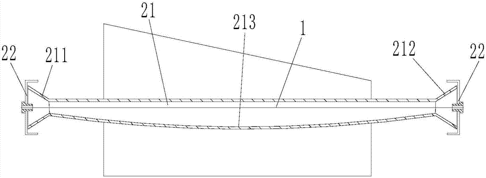
[0053] Such as figure 1 As shown, an annealing mechanism is used for annealing the wire body 1 after drawing, and the annealing mechanism includes an annealing tube 21 . The two ends of the annealing tube 21 are the wire inlet 211 and the wire outlet 212 respectively, and the inner wall 213 at the bottom of the annealing tube 21 is a downwardly concave arc. The wire body 1 enters the annealing pipe 21 from the wire inlet 211 , and is discharged from the wire outlet 212 after being heated by the annealing mechanism. In actual use, the wire body 1 enters the annealing tube 21 from the wire inlet 211 and is discharged from the wire outlet 212 by pulling the wire body 1 to keep the wire body 1 in a tensioned state. But because the wire body 1 enters the annealing tube 21 and will be heated, at this time due to thermal expansion and contraction, the part of the wire body 1 in the annealing tube 21 will sag, and the bottom inner wall 213 of the annealing tube 21 is used to be a dow...

Embodiment 2

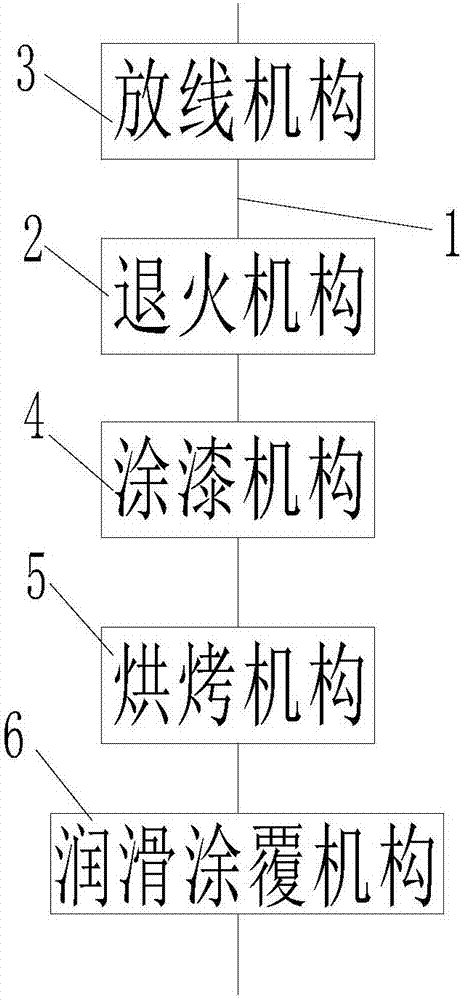
[0057] On the one hand, the present invention also provides an enameled wire production system, which is used to paint the wire body 1 after wire drawing, such as image 3 As shown, the enameled wire production system includes: the annealing mechanism 2 in the first embodiment, as well as the painting mechanism 4 and the baking mechanism 5 . The wire body 1 passes through the annealing mechanism 2, the painting mechanism 4 and the baking mechanism 5 in sequence. After the wire body 1 is annealed by the annealing mechanism 2, the paint liquid is applied to the surface of the wire body 1 through the painting mechanism 4, and then passed through the The roasting mechanism 5 roasts the wire body 1 .

[0058] It should be noted that after the thread body 1 is annealed by the annealing mechanism 2, the surface of the thread body 1 can be cleaned first (for example, the surface of the thread body 1 is cleaned with felt), and then the paint solution is applied by the painting mechanis...


PUM

PropertyMeasurementUnit
diameteraaaaaaaaaa

Abstract

The invention provides an annealing mechanism and an enameled wire production system. The annealing mechanism comprises an annealing pipe; two ends of the annealing pipe are respectively a wire inlet and a wire outlet; the bottom inner wall of the annealing pipe is a downwards recessed arc; and a wire body enters the annealing pipe from the wire inlet, and is discharged from the wire outlet after being heated by the annealing mechanism. The annealing mechanism has the advantages of capability of preventing the surface damage of the wire body in the annealing process and guarantee of the painting quality of the wire body.

Description

technical field [0001] The invention relates to the technical field of enameled wire production, in particular to an annealing mechanism and an enameled wire production system. Background technique [0002] Enameled wire is the most representative product among electronic wires. It is composed of conductor and insulating layer. The bare wire is annealed and softened, and then painted and baked many times. However, it is not easy to produce products that meet both standard requirements and customer requirements. It is affected by factors such as raw material quality, process parameters, production equipment, and the environment. Therefore, due to different production processes, the mechanical and chemical properties of enameled wire , Electrical properties, thermal properties, etc. are also significantly different. [0003] At present, in the production of enameled wire, especially in the process of annealing the drawn wire body, it often occurs that the wire body is bumped ...

Claims


Application Information

Patent Timeline
Patent Type & Authority Applications(China)
IPC IPC(8): C21D9/52C21D1/26H01B13/06H01B13/16
CPCC21D1/26C21D9/525H01B13/06H01B13/16
Inventor 赵冰蔡军臣杜茂林周楚江李飞
Owner 格力电工(马鞍山)有限公司
Why Eureka
Try Eureka